
In this blog post we reveal a case study for problematic aluminium hood-outer whereby splits were observed along the part during try-out. Those splits were however not detected in the initial forming simulations, which allowed TriboForm to rescue the part with integrating a true tribological behaviour.
The nightmare of every simulation engineer is to hear back from the tool shop that a part, which appeared green (safe) in the forming simulations, turned out to be critical in try-out. Naturally, it is of great importance to detect the sources of discrepancy between simulation and try-out, and preferably by using simulations rather than the conventional approach of trial and error in the tool shop. The latter is impractical, time consuming and costly.
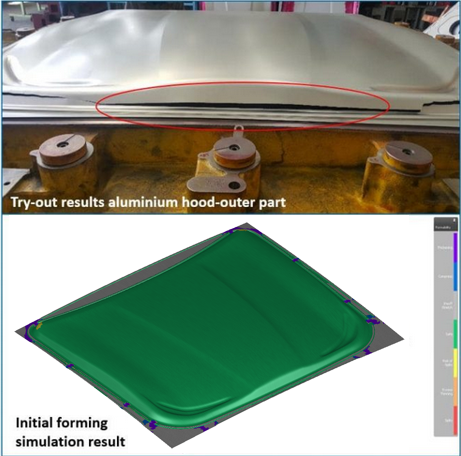
Figure 1. (top) Aluminium hood-outer part showing splits along long edge of the hood-outer part in try-out, which was not detected in the initial forming simulations using Coulomb friction (bottom).
While it is well known that the aluminum parts are highly sensitive to friction and lubrication conditions, the industry standard is to use a constant (Coulomb) coefficient of friction in forming simulations. To tackle the issues in try-out production, the engineering team decided to enhance the description of friction and lubrication conditions in their forming simulations. A numerical study was performed to investigate the effect of friction and lubrication conditions on the aluminium hood-outer part quality using the TriboForm software together with the AutoForm software.
The goal of this work was to more accurately simulate the try-out conditions, especially capturing the splits, by integrating advanced friction models in the forming simulations. This enhanced simulation model together with the initial simulation model, which utilizes a constant Coulomb coefficient of friction of µ = 0.15, are compared to the try-out results at different drawing depths. This enables to follow the split formation as a function of drawing depth and validate the simulation results incrementally as well.
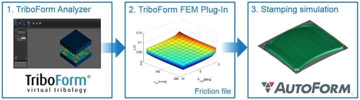
Figure 2. The TriboForm software enables its users to define advanced friction models to be used in AutoForm simulations.
To more accurately account for friction and lubrication conditions in sheet metal forming simulations, the TriboForm software is used. An overview of the workflow is shown in Figure 2. The TriboForm software allows for multi-scale modeling of a time and locally varying friction coefficient under a wide range of process conditions. The TriboForm Analyzer enables its users to select a tribology system corresponding to the specification of the sheet material, lubricant and tool material used in the forming process. For the selected tribology system, a friction model can be generated and exported from the TriboForm Analyzer. Next, the friction model can be imported in the AutoForm software using a TriboForm FEM Plug-In, replacing the constant coefficient of friction. In addition, the TriboForm software enables the generation of multiple friction models for varying settings of e.g. the sheet roughness, tool roughness and/or lubrication amount. This enables the user to simulate varying tribological conditions rather than a single scenario, providing a deeper insight into the role of friction and lubrication on the forming process.
An overview of the applied tribology system of the hood-outer part is summarized in Table. 1. The aluminium sheet material used for the hood-outer part is an AA6xxx series. A hotmelt lubricant is applied to the sheet material. A lubrication amount of 0.6 g/m2 and 1.2 g/m2 was evaluated, as these amounts are commonly applied to the sheet material by the supplier. Cast iron tools are considered with a tool roughness of 0.6 µm and 0.8 µm. These roughness values are based on measurements performed on the try-out tools. For this tribology system, a TriboForm friction model is exported from the TriboForm Generic Library and utilized in the AutoForm forming simulations.
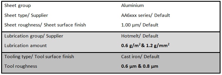
Table. 1. Specification of tribology system of the hood-outer part
The initial simulation result is shown in the bottom image in Figure 1, visualizing the distribution of maximum failure for the hood-outer part. It shows critical spots in the corners of the hood-outer part, but no splits are detected along the long edge of the part as observed in try-out.
Figure 3 shows the simulation results of the enhanced simulation model using the TriboForm friction model. The distribution of maximum failure on the final part for different tool roughness’s and lubrication amounts is visualized. It can be clearly seen that the simulation model including the TriboForm friction model significantly improves the agreement between the simulation results and try-out. The critical spots are detected along the edge of the part, corresponding to the observations in try-out. In addition, it can be seen in Figure 3 that both the tool roughness and lubrication amount affects the maximum failure. That is, a higher tool roughness or lower lubrication amount results in a higher risk of failure.
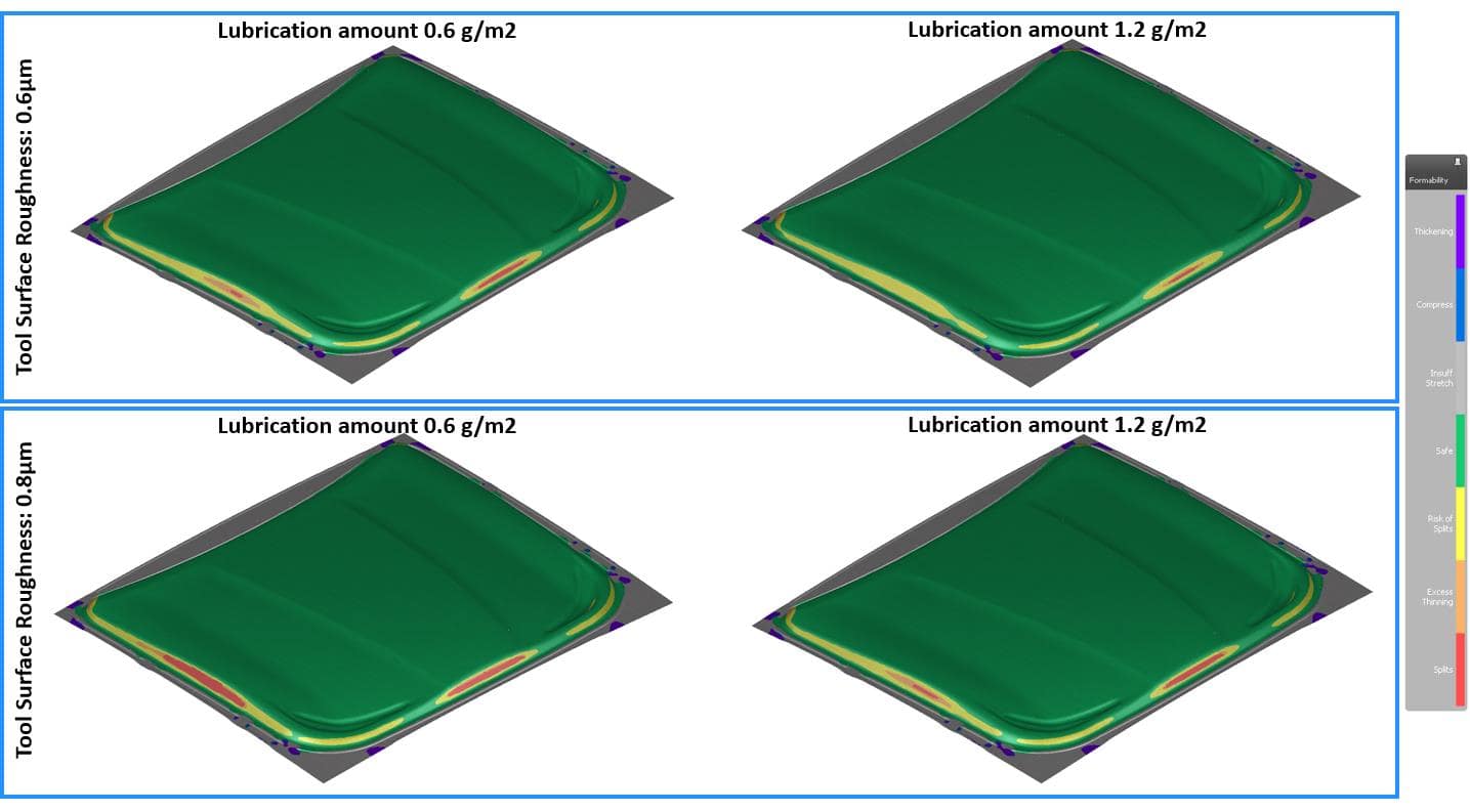
Figure 3. Enhanced forming simulation results using TriboForm friction, showing the distribution of maximum failure for the hood-outer part for different tool roughness and lubrication amount.
As a final step, the try-out results at different drawing depths was studied. The press was stopped -10 mm, -5 mm and -2.5 mm before closing. See the top image in Figure 4. The part shows no splits at -10 mm, after which the part becomes critical at -5 mm, and splits at -2.5 mm. This exact behavior and split location is also observed in the simulation results using TriboForm friction, see the bottom image in Figure 4. A summary of the results is given in Table 2, showing an overall good agreement between try-out and simulation results using TriboForm friction in terms of split formation.
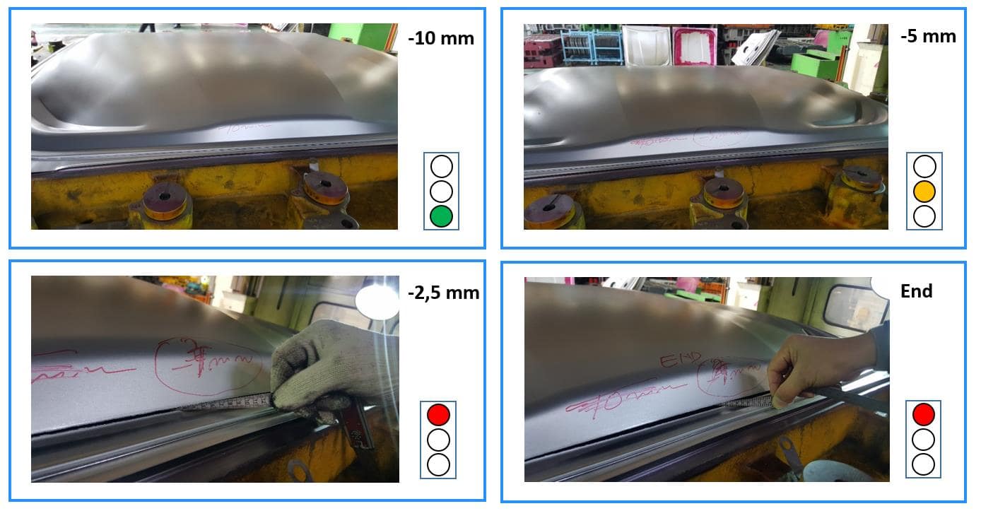
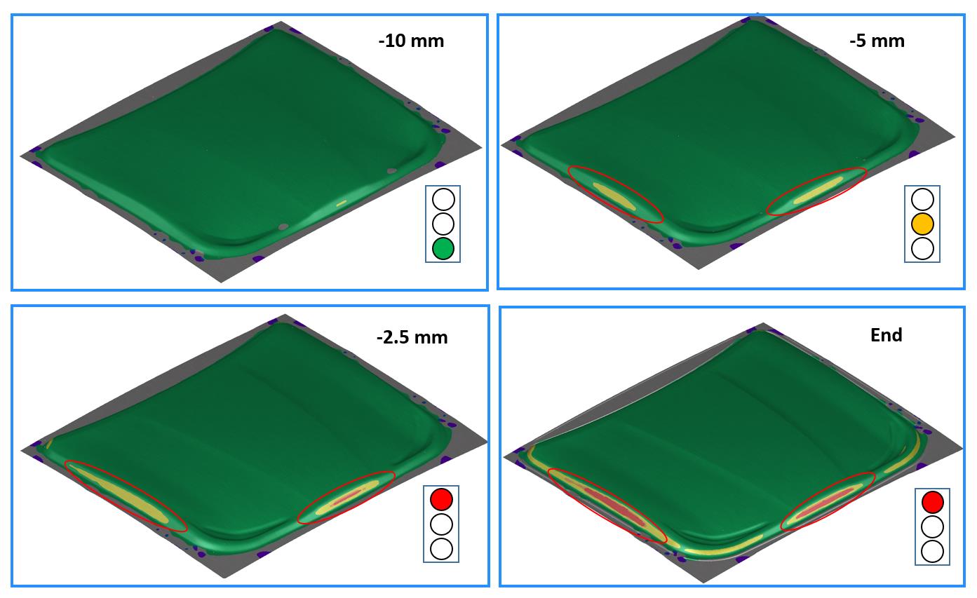
Figure 4. Try-out and simulation results for varying drawing depths, showing a good agreement between the split location and formation in time in try-out (top) and simulation (bottom)
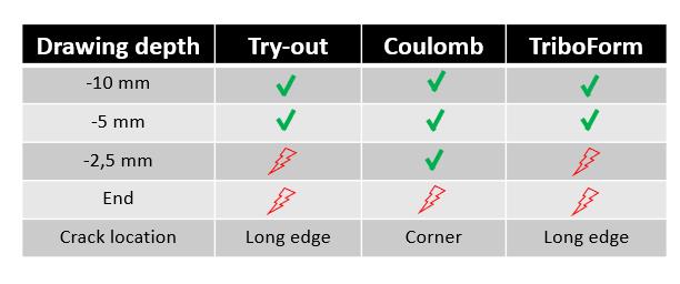
Table 2. A summary of the split formation in time between try-out, simulation results using constant Coulomb friction, and simulation results using the TriboForm friction model.
This case study clearly demonstrates the importance of an accurate description of friction and lubrication conditions in forming simulations of aluminium parts. For the initial simulation results using Coulomb friction, the critical location was simulated in the corners of the parts which did not correspond with tryout production. The agreement between the simulation results and try-out improved significantly when using the TriboForm friction model. That is, the splits location and formation were correctly simulated.
Thank you Chanho Lee, from AutoForm Engineering Korea Ltd, for this great post!
New readers, now is the perfect time to sign up to our blog to follow and get updates once per month on our top most-read posts!


")


