A Die Designer’s Change in Perspective on CAD vs. AutoForm in the Initial Simulation Setup
Bryan Lang has a lot of experience in the tool design and die world. Formerly he worked at Toolcraft Products in Ohio, in its tool and die shop. Under their employment he designed tools in NX, before passing his work onto the other departments. Working with toolmakers and project managers from the beginning to the end, he was able to help ensure a smooth and efficient process throughout the life cycle of the product. Now, after working at AutoForm for just six months he shares his eye opening moments for other designers and process engineers.
Bryan, thank you for this post:

Time, the one thing none of us have enough of. In the tool and die industry this is becoming increasingly true. Time constraints on the life cycle of a product are continually narrowing. Products are being pushed to the market as quickly as possible, putting each phase of the manufacturing process under certain risks and strains. The demand for new procedures, software, etc. is increasing to accommodate this change, with simulation software at the forefront.
Designers, however, are generally not able to sacrifice the time from their normal work cycle in which they have been treading for years. I personally know the demanding process involved having worked as a die designer since 1996. Dedicating time for training and learning new software, or even just learning some new techniques is extremely difficult. Having stood on the other side, I can say that from the designer’s position it’s even hard to imagine why I would even want to spend time learning something new when my process already works. This is also not to mention the lack of design support these days.

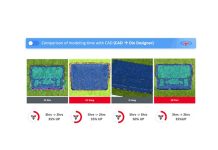
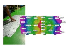
Fig 1: Which is which? NX vs. AutoForm
One way that AutoForm has always tried to help with this, is by making their software more and more user friendly. Allowing full-time experienced designers to quickly create surfacing for all stages of the tooling process, from creating the draw binder and addendum, to multi stages of a form or wipe (whether or not they are in a cam setup or vertical motion) and hemming tooling to developed trim lines. A Designer knows what he knows, and generally will create all the surfacing for his or her tooling in their CAD software on hand.
Now coming from the design side of things, and having worked with a major CAD system for over 20 years, breaking away from this “norm” of designing strictly in CAD was a task that seemed almost impossible, as many CAD designers might consider. Creating the surfacing in the CAD, exporting it out into AutoForm seems to be the “easy” way to go.
AutoForm allows you to bring the CAD geometries into the software, setup the tooling, including travels and pressures, and directly run the simulation. It gives you the formability results that you need before deciding to go ahead with your setup or start making part concessions. But then you can go back into CAD, make the changes that you think will correct the issue, export again and bring that back into AutoForm. Repeat the cycle and you’ll get results. Eventually with enough iterations and changes in CAD you more than likely will come up with a process that works and will allow you to move on to the next phase of manufacturing.

But there can be an easier way, and even a quicker way. You can import your native part geometry into AutoForm which reads industry standard formats including, Catia, NX, Visi, Solidworks, Step and Iges. You’ll then be able to lay out your design process including draws, trims, forms and wipes, and even hemming and hotforming. You’ll further be moved into the DieDesigner stage where your tooling geometries are created off of your imported part, and then your simulation run.
The greatest benefit in using DieDesigner is that you can achieve the process so much faster. Coming from the side of a former designer, for me that is one of the biggest things. Consider that without this software you could spend a good part of a day just doing a draw (a D20 operation) setup, going over your binder ring, your addendums etc. Even laying out your trim lines onto your addendums and binder surfaces accumulates more time. Having learnt DieDesigner, I now can quickly build an addendum and binder surface allowing me to run a “trimcheck” that will lay out a trimline, assuring proper geometry setup and tooling conditions. In addition, it is also possible to run an “early feasibility” check on the modeled die by running a Formcheck, the one-step formability simulation feature that helps designers to detect risky areas and immediately work on countermeasure before running the incremental simulation. With the same geometries we run the full incremental simulation to evaluate the amount of springback and look for modifications that would reduce it, if necessary, ensuring “compensability”.

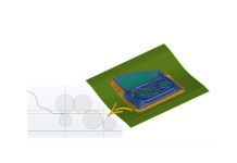
Figure 4 – Efficient Geometry Workflow with AF-DieDesigner
While it depends on what kind of part you’re making, some parts I can now setup in a matter of minutes. Larger, more complex parts of course take more time, but what previously took me ten hours of work, in my experience can now be done in just a couple of hours. All of this opens the possibility of getting more focused on making the process work remain under control for total cost, with a knock-on effect for total cost for tool maker, part cost, material consumption etc.
Only at the end of this process and when you’re happy about the results you came up with move to CAD and generate the high quality tool surfaces which will be used for milling.

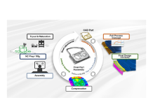
Figure 5: Products positioning along the process chain
Figure above shows the two possible design approaches (with and without concept surfaces created with AutoForm-DieDesigner.
Looking back, I wish I had taken the time to understand, trial and learn DieDesigner. Attending the Advanced Die Face Development training was a huge eye opener and will also give you more confidence in your simulation setup. With more experience and training, you’ll be able to supply better answers with your projects and give reassurance to customers early on in the product’s life cycle. Most of all, if you invest time to learn it, the new resulting time savings means having more hours to dedicate to obtaining more projects and customers.
Thank you Bryan for this great post. Readers, don’t forget to stay updated once per month on our latest posts by subscribing to our blog.
*cover image courtesy of Karmen.


