
The Evolution in Draw Bead Modelling and Best Practices
There has been plenty of approaches implemented aiming at substantially decreasing modelling and computation times for assessing the process design for forming and trimming of deep-drawn parts. Especially for the early feasibility check and the later redesign cycles of the applied process tools, there are favorable options requested to speed-up result generation. In this sense, one of the most effective approaches is using analogy models for draw beads. Much experience has been gathered over years inside the AutoForm-organization. Thus, the current version of the Advanced Line Bead Model embraces a whole set of valuable responses coming from customers and takes into account findings in most recent research.
But let’s start with simpler things. One representation of real geometrical drawbeads could also be the Continuous Line Bead Model. Its main characteristic is that restraining forces are assigned to a center line by means of force factor settings which remain constant during the whole drawing process. Secondly, uplift forces are either derived from these values or defined in terms of their influence by corresponding factors. Plastification effects in the bead area are taken into account. So, this is clearly an option for real early feasibility checks and the determination whether or not draw beads are required.
A more advanced and recommended choice is the Adaptive Line Bead Model. Here, the restraining and uplift forces (as well as thickness reduction and plastification effects during bending) are computed during every single time increment. This allows for a much higher level of accuracy. In contrast, the Constant Line Bead Models conducts the restraining force calculations only once on the basis of the geometrical bead model.
But how accurately can this model handle real drawbead effects? This model is capable of taking all aspects of the sheets’ behavior into consideration for the computation of the current restraining force – such as thinning, restraining induced by the beads, and the uplifting forces introduced into the binder.
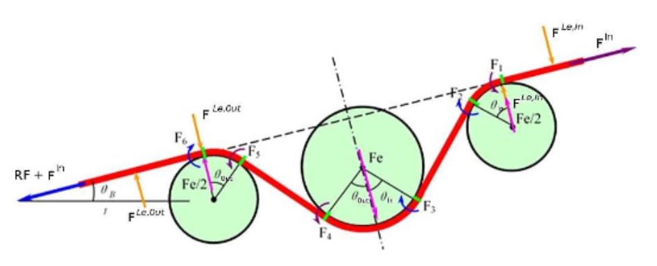
Fig. 1 Equivalent Drawbead Model.
By incorporating equivalent models (Fig. 1) an outstanding level of accuracy can be reached. Tests can prove the validity of such an assumption, like the popular Numisheet-benchmark [1] or others applying both, the regular Equivalent Drawbead Model, and the enhanced Equivalent Drawbead Model (Fig. 2).
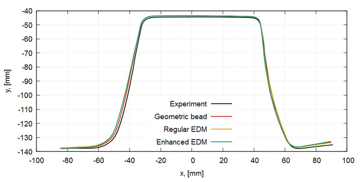
Fig. 2 Comparison of bead models to geometric beads.
Table 1 shows a comparison of simulation results demonstrating how effective this approach truly is. A comparison of the computation times, linked to an assumed regular or enhanced Equivalent Drawbead Model (EDM), has led to the remarkable results shown below.
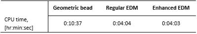
Table 1 Computation time in dependency on geometric bead and Equivalent Drawbead Model.
Another powerful tool to optimize draw bead modelling in an efficient manner is AutoForm’s Flattening/Unflattening option (Fig. 3). This feature combines the advantages of both the geometrical and line bead models. After all, there is still a main advantage of the geometrical beads to draw from, yielding far greater accuracy for the prediction of wrinkling of the sheet during the closing of the die. Also, the outline of the blank is represented far more accurately. Here, the flattening/unflattening process enables a good prediction of the real forming behavior of the sheet, without interfering with the main reason to use line bead models in the first place: substantial computing time savings.
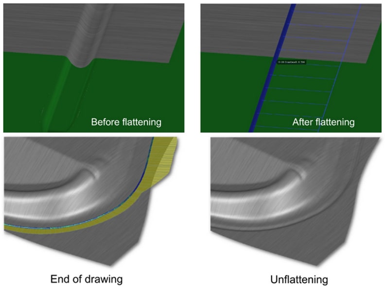
Fig. 3 Flattening and unflattening in combination with the Adaptive Line Bead Model.
Therefore, the advised concept consists of the following steps: The early process engineering steps may be carried out using the Constant Line Bead option. EBZ starts with the Constant Line Bead model in practice. At this time more conceptual loops are required. This mainly serves to define the required beads and bead segments, their specific position and general shape. During this iterative process, speed and fast turn-around times are most important. Thus, the factor-based solution, taking into account the principal effects, is the preferred one.
Once the process definition has reached a certain maturity level, in terms of existing input geometries, and has been proven as feasible, the next step can be taken using the Adaptive Line Bead Model. This includes the Flattening/Unflattening option. This selection is most capable of representing the real conditions. Now there is still remarkable potential for time savings, whilst the computations may reach an outstanding level of accuracy, even close to what is experienced with 3D-beads.At this stage the combination of positioning the beads and the virtual shaping of the beads (via Systematic Process Improvement) is recommended. Design parameters can here be defined which will be varied in a whole set of so-called realizations. By means of a meta-model, the impact of these parameters on the part quality can be determined and a parameter`s best fit can be easily generated.
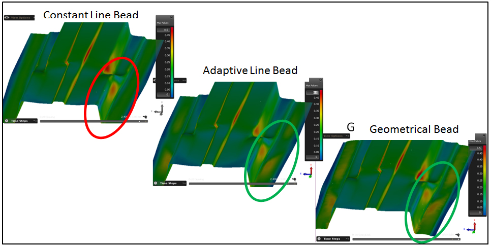
Fig. 4 Result and accuracy refinement applying corresponding bead modelling options. Curtesy of EBZ SysTec GmbH
In completing the final design phase, a user can still engage the geometric beads for validation purposes, even though there is limited potential for improvements in terms of quality. Using this combined approach one of our customers, EBZ SysTec GmbH, has shared their approved practice for final validation (Fig. 4). They prefer to simulate the closing process of the tools with geometrical beads [2]. For the drawing process they use the Adaptive Line Bead Model. Springback is then simulated by applying geometrical beads again. The Flattening/Unflattening option serves to switch back and forth between these states. Therefore EBZ SysTec GmbH experiences accurate and reliable results for their tool design processes while using the most efficient analysis options in each stage of process engineering.
For new readers; join our group of subscribers by signing up to our blog as we continue to send out sheet metal forming news. Zero marketing emails are sent. You’ll receive just one update per month on our top metal forming posts to your inbox.
| [1] | T. Buranathiti and C. Cao, “Benchmark Simulation Results: Automotive Underbody Cross Member (Benchmark 2),” in International Conference and Workshop on Numerical Simulation of 3D Sheet Metal Forming Processes, Detroit/Mi, 2005. |
| [2] | T. Schönbach and J. Wieland, “Effektive und genaue Modellierung von Ziehsicken in der Umformsimulation,” in Innovative Blechumformung in der Automobilindustrie 2018, Nürtingen, 2018. |


