
Cross-Checking the Impact of Geometric Changes for Springback
In this article Austin Davis, Application Engineer from AutoForm USA, outlines how changing geometric features of your part design play an important role in controlling and reducing springback. He shows two basic changes you can apply to your part designs now and demonstrates their impact through simulation results for the same part made from three different materials for you to compare.
Reducing and controlling springback is crucial to stamping. While there are methods to do so, by looking at the process, or the type of material, a very important aspect to the amount of springback a part will have is based on the design of the part. There are various features that can be designed into the part that will have an effect on the springback after forming, allowing some control. Although there are many different aspects of part design, we will be focusing on three specific features. The first is an additional shape added to a flange radius. The second will be a cutout in the bottom of a flange. The third is the material type being used to make the part.
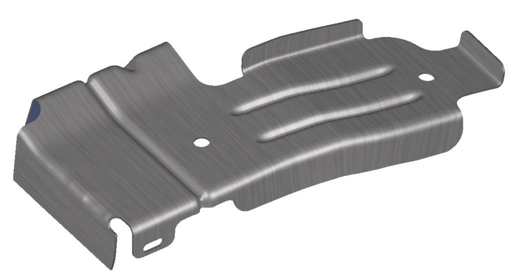
Fig. 1: Original part design.
In order to best explain a few of the part design features that affect springback, a baseline file will be used that has these features in separate areas of the part. Geometry changes will be made to the part in order to compare springback results and see the effect of part design on springback.
When looking at ways to reduce springback by changing the part design, the first thing that can be looked at is the addition of a shape or a dart into the radius of a flange. Below we can compare the original design to the countermeasure design. The added part geometry helps reduce the springback seen on the flange by its added plastic strain as well as much more geometrical strength. The best way to reduce springback is to have as much of a part as plastically deformed as possible. This can be achieved in many ways including reduction features added to the part geometry as shown in this example with the addition of the darts to the radius.
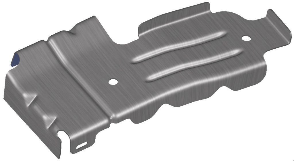
Fig. 2: Dart added to the original part design.
When we compare the two parts seen below they are the same, but the part on the left is just a plain (original) radius, while the one on the right has two darts. The severity of springback found in the modified geometry has been reduced by over 50% when compared to the original geometry! The springback reduction is limited to the areas that are in close proximity to the added darts.
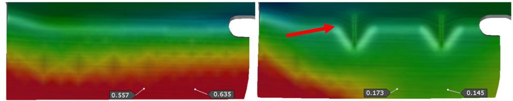
Fig. 3: Before & after showing minimized springback resulting from the added darts.
Another part design feature that can be added to reduce springback on a flanged area is the cutline on the edge. This helps by reducing the localized springback in these areas due to stretch or compression along the part boundary. Here we compare the nominal shape with that of another part with the same geometry, but with the notch added. When looking at the results below it is clear that the total amount of springback is reduced in the area local to the cutouts in the flange area. With both of the techniques that have been reviewed the part design aspect of reducing springback is limited to the local areas of design. Different techniques and methods used for part design that are useful to impact the springback of a part are generally going to be localized.
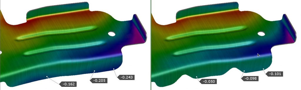
Fig. 4: Before & after, showing cutline additions to part edge.
Although the two previous methods of reducing or controlling springback by way of part design are the focus, there are other things to consider when looking at part design. Sometime the geometry of the part cannot be changed because of constraints dictated by the adjacent parts it is going to be assembled with, and sometime the geometrical features are not so effective because of the position where they can be inserted. The material for the part is also crucial for springback. Typically aluminum will have much greater springback than steel. As the yield strength increases so too does the springback for the part become magnified. This works together with the different Modulus of Elasticity for different materials to increase or reduce the springback experienced for the same shape. Below are images comparing the amount of springback found using different materials. Here we see that using an Aluminum material will generate more springback on the same part as compared with low carbon steel. We can also see that high strength steel will have a greater amount of springback.
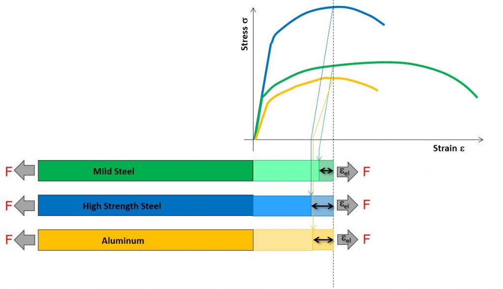
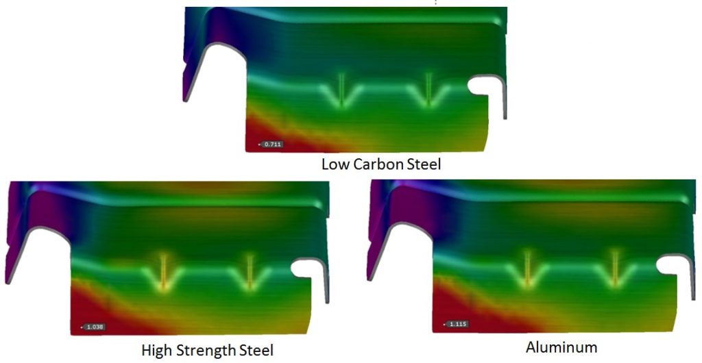
Figure 5: The above graph shows the springback for mild steel, high strength steel, and aluminum.
After taking a closer look at a few different geometric design examples as well as material type, it is clear that part design plays an important role in controlling and reducing springback. When first designing a part, some of these concepts should be kept in mind in order to create a springback scenario that can be more easily fixed by processing. Talk with your colleagues and find out what tricks they have been doing to achieve feasible part design. You can always contact AutoForm for professional advice.
New readers don’t forget to sign up to our blog! We’ll never send you any marketing emails. You’ll get a once per month update on our latest top post!


