Lately, one of the most frequently asked questions in metal forming simulation has been “Can your software model the effects of a servo press?” The answer to this question has been YES and NO. It’s YES because, with most metal forming simulation software programs, we have the capability to define ram speeds and therefore can model the potential of the die to close the die at variable speeds, much like the servo press. It’s NO because in many cases, the ram speed would seem to not influence the simulation of the material deformation, especially when using hardening criteria with no strain rate sensitivity and a single friction coefficient value.
Measuring the effect of cycle time and ram speed on sheet metal deformation is more complex than simply telling the simulation that the tools are closing faster. The effects of speed on the mechanics of the press and die tooling, alignment, friction behavior, lube temperature, and force distribution are largely overlooked in the way that many analysts set up their stamping models. Today, simulations can be augmented by introducing the strain rate sensitivity for a material, easily input in many cases and commonly available. But not until the more influential interactions at the tool-lube-sheet interface can be modeled well will the potential of modelling ram speed be more fully realized.
The role of lubrication in the stamping system
In our previous post on the stamping system, several environmental variables within production sheet metal stamping are mentioned. In that post we listed variables such as blank surface, blank coating, tool surface, tool coating, and blank/die lubrication. These variables are often grouped together into one variable when conducting an engineering analysis as the friction coefficient.

The blank lubrication, die substrtate and coating, and blank material and coating are key friction drivers
| Blank/Coil | Production Line | Die |
| Coating (if any) | Lubrication (if any) | Die surface and coating |
| Mill oil (friction coefficient) | Lube (friction coefficient) | Tool and surface condition |
| Grain and rolling direction | Lube thickness and distribution | Temperature |
| Substrate metallurgy | Ram speed (cycle time) |
A common problem facing many who run stamping simulations is what friction coefficient to use for running a computer simulation. Anybody who has run a metal forming simulation has faced this problem; inquiries about what values to use are often met with answers such as these:
- Cast iron tool with no chrome, galvanized sheet, and mill oil? 0.15 should be reasonable
- Cast iron or steel with chrome, galvanized sheet, and blank wash fluid? 0.12 is a good start
The simplification of the complex tribology relationship between the sheet, tool, and any interface between the two surfaces into a single characteristic value, like the Coulomb friction modeling used in most stamping simulations, has provided the industry with an easy-to-use and fairly robust modelling input. Coulomb friction has allowed us to reach the very high level of accuracy and predictive value that is the current state-of-the-art in stamping simulations.

coulomb friction assumes that friction coefficient is constant
Typically, with metal forming simulation, we enter a single value for friction. This is a simple Coulomb friction that is presumably the kinetic, sliding, friction in the die. When nothing else is known, we still need to have a value as an assumption, and we often make our best educated guess. However, friction behavior in a real-life die is not so simple. The lubrication between the sheet metal and the die could present behavior as if a hydrostatic barrier exists between the two surfaces. That barrier would certainly change as the sheet is deformed over the tool, creating localized contact pressure differences. Additionally, viscous fluids (such as lubrication fluids) will perform differently when the sliding velocity between the two media increases and decreases. The performance of the lube should also reflect this as well.
But the potential exists that using such simplifications of the friction and lube behavior during simulation could lead to cases of over-engineering and in other cases underestimation of failure. Applying the basic friction characteristic could lead to significant overspending of resources trying to resolve forming issues that, in reality, might never arrive. Similarly, the simple Coulomb friction model could result in forming issues being underestimated during engineering, leading to a demand for tools that might need additional lubrication to achieve the results needed during production to match the design intent.
The use of a single friction value could lead to under prediction of failure

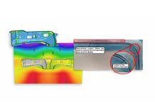
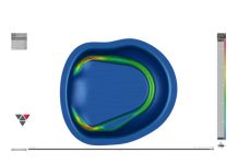
Pressure distribution and relative velocity during material deformation varies over the surface of sheet and tool, which can affect the coefficient of friction between the sheet, lube, and tool
To address these complexities of lubrication modelling, we introduced pressure- and velocity-dependent friction models in recent versions of our software. Engineers can use these models to better represent the performance of lubrication under different pressure and velocity regimes. However, these lubrication models often require the user to define a reference pressure, pressure exponent, reference velocity, and velocity factor. But now the question arises as to what values should be selected for these input variables.
 This assumes that the user has access to lubrication data on the coefficient and relative velocities and pressures, which – in reality – is often not the case. In fact, debate in the tribology (lubrication) field persists as to which friction testing methods best reflect reliable measurement of friction coefficients, especially when trying to simultaneously recognize pressure and velocity dependencies of various lubricants in the tribological system. http://www.mwfmag.com/mwf/docs/tlt_ChallengesMFF.pdf and http://link.springer.com/referenceworkentry/10.1007%2F978-3-642-22647-2_230 and http://papers.sae.org/2010-01-0990/

Source: Springer Sheet metal forming lubricants
However, new advances, announced recently by TriboForm B.V., indicate that a solution could be at hand. They claim that their dynamic lubrication simulation enables users to define different sheet metals, tooling metals, and the surface of each, with lubrication type and distribution that is then used to conduct a variety of simulations. These simulations develop a relationship between the instantaneous coefficient of friction for different elements under the various conditions likely in the die, providing the user with the needed inputs for pressure sensitivity and velocity dependence while stamping.

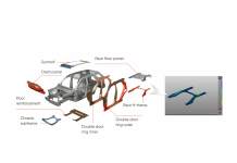
Triboform considers the blank and tool surface characteristics, lubrication behavior during deformation

Triboform considers the blank and tool surface characteristics, lubrication behavior during deformation
TriboForm promises a virtual tribology interface with stamping FEA programs such as AutoForm. Their plug-in enables the user to merely characterize their sheet-tool-lube interface in terms of type of sheet, type and amount of lube, and tooling surface, and lets the virtual tribology engine within the plug-in determine the resulting friction behavior, taking into account pressure gradients and velocity.
This is certainly a very promising change in the engineering, design, and analysis of sheet metal stamping processes, which should allow for further improvement in stamping time to market, part quality, and tooling/production costs.
To read more about TriboForm and their recent release of software, please refer to these links:
http://www.triboform.com/ref/volvo/
http://www.triboform.com/ref/daimler/
We have invited TriboForm to expand on this topic for our blog. If you have specific questions about how their solution works, please ask them here. We will pass those specific inquiries on and post their responses soon.
Stamping and Dies Tech Group and Metal Forming Simulation Tech Group meeting
- Wednesday May, 11, 2016
- 1:00 PM Eastern Daylight Savings Time (US)
Meeting number: 649 116 325
Meeting password: Stamping
https://smeweb.webex.com/smeweb/j.php?MTID=m2bb6c12127c229bb4dab2133493b23f9
Audio connection:
- 1-877-668-4493 Call-in toll-free number (US/Canada)
- 1-650-479-3208 Call-in toll number (US/Canada)
- Global Call-in numbers
- Access code: 649 116 325
The meeting is free to SME members and guests.
Servo press feasibility
The ability to predict the full benefit of servo press programmable velocity profiles will depend highly on the more widespread recognition of pressure and velocity dependent friction modelling by the stamping simulation community.







Hello,
this is very interesting article. What do you thing about aluminium part? There is recommendation For iron steel :
•Cast iron tool with no chrome, galvanized sheet, and mill oil? 0.15 should be reasonable
•Cast iron or steel with chrome, galvanized sheet, and blank wash fluid? 0.12 is a good start
And Aluminium parts? Is coefficient the same or not?
Thanks
The characteristics of aluminum are that it is much more abrasive with greater tendencies to “stick” to the tooling. It will often have a more aggressive lubrication applied. Blank wash and even in-tool lube systems are sometimes used.
Coefficient of 0.11-0.17 we have seen used. In some cases 0.09 or 0.20 could be argued. The point is that this new concept of tribology simulation could potentially address this question better than a question posted to a blog or googled information.
Maybe not the answers you may have been hoping for but thank you for reading the blog.
A recording of the WEB presentation is posted here:
https://youtu.be/B-2ppYlcPEs
This post helped me to learn about the lubrication in stamping system. Well written and easy to understand. Thank you for sharing your thoughts.
http://www.pro-sim.com
The cases were much helpful for me,
Can automotive stamping parts / products be produced defect free.
Thank you
TriboForm can definitely help to achieve defect free products; of course together with careful selection of other process engineering factors.