Various software programs based on Finite Element Method (FEM) have been developed by universities, research institutes, and companies, aiming to meet the diverse needs of modern engineering. These developments have used different implementation concepts, which have important implications for how the software is applied in practice. It is therefore important for designers, engineers, and industrial decision-makers to familiarize themselves with the general application characteristics of the different implementations of numerical simulation using FEM. This knowledge allows them to plan, implement, and evaluate the application of these programs as efficiently as possible, considering their objectives. The aim of this article is to detail an important technological aspect that characterizes the different ways of implementing numerical simulation using FEM: the approach with which the programs are developed.
The Different Approaches:
There are essentially two approaches that FEM software developers have adopted to implement their simulation solutions: the “horizontal” approach and the “vertical” approach.
The “Horizontal” Approach:
In the horizontal approach, FEM implementation is designed to offer users the broadest possible range of options for setting up their simulation models. This allows a wide variety of problems to be analyzed using the same program. Different types, topologies, and formulations of finite elements are implemented, as well as numerous calculation options, convergence controls, and criteria for evaluating results. These options enable users to define the specific details needed for each case they wish to analyze. For each physical phenomenon under study—such as the calculation of structural stresses, thermal effects, impacts, vibrations, and buckling—a different model with specific characteristics must be prepared.
This approach makes these programs highly versatile and powerful, allowing them to be used for the most diverse applications. However, it requires a high level of knowledge and experience with FEM concepts to ensure that the model is appropriate for the phenomena being studied and that the calculation is accurate and efficient. Since the user is responsible for setting up the simulation, careful attention must be paid to details such as element selection, mesh refinement, and the application of boundary conditions. Otherwise, the results may not be accurate.
Figure 1 illustrates examples of FEM simulations prepared using the horizontal approach, where three different models are used to analyze the stresses of the same structure, all yielding similar results:

Figure 1: Different simulation models using solid, shell, and beam finite elements to represent the same structure. Each model has different characteristics and computational performance, but all provide similar results.
The “Vertical” Approach:
In the vertical approach, program developers are responsible for creating systems that automatically generate the FEM simulation models needed to represent the phenomena being simulated in the most appropriate and efficient way, rather than leaving this task to the users. Details such as the type of element used, mesh refinement, and calculation convergence criteria are all applied automatically by the program according to predefined criteria. These programs are also equipped with interfaces that “translate” the technical terms used in engineering and design practice into the mathematical parameters needed to set up the simulations and perform the calculations efficiently. As a result, users interact with the software using the concepts and terms familiar to them in their everyday work, and there is little risk of setting up models that are unsuitable for the phenomena being studied, which minimizes the possibility of mistakes.
However, the trade-off is that vertical systems can only be used to analyze the specific problems for which they were developed. Unlike horizontal systems, they do not offer the flexibility for users to define their own models for a broad range of applications. Data input and mathematical details are restricted to ensure consistency with the desired analysis, preventing modeling errors. In this way, FEM implementations using the vertical approach are typically restricted to a single application, often the analysis of a specific manufacturing process such as casting, plastic injection, or sheet metal forming. What the programs gain in efficiency, accuracy, and safety, they lack in scope and versatility.
Implications for Implementation and Application:
The two different approaches to implementing FEM simulation programs have distinct implications for their adoption and practical use by companies using this technology.
Programs Using the Horizontal Approach:
When developing new parts, systems, or products to meet various operating requirements—such as resistance, efficiency, durability, and low noise emission—horizontal programs are the most suitable. Their versatility allows for multiple types of analyses, from determining natural vibration frequencies and temperature distribution to calculating structural stresses, fatigue durability, resistance to buckling, impacts, and other criteria necessary for project approval. Using horizontal systems, specialist engineers can perform all of these analyses with a single software, reducing acquisition costs, speeding up implementation, and simplifying day-to-day use. Therefore, the broader and more versatile the modeling options offered by the program, the better it serves these needs.
In this case, the user’s responsibility is generally limited to identifying potential issues with the new products under development and reporting their findings to product designers and engineers—typically through engineering reports—so they can make the necessary design modifications. The updated designs are then resubmitted to the FEM specialists, who rerun the analysis to ensure the issues have been resolved. This two-way process allows FEM experts to dedicate themselves solely to acquiring the knowledge and experience needed to build the most accurate and efficient simulation models, since they don’t have to divide their time between simulation tasks and other design-related activities like modifying CAD geometries, studying design standards, selecting material criteria, or conducting assembly feasibility.
As a result, users of horizontal systems become highly specialized and experienced in the simulation methods, but they lose some contact with the other activities involved in project development as a whole. Careful work must therefore be done to integrate the design and analysis teams to ensure that both work in a cooperative and harmonious manner, with an efficient data flow that allows for the rapid exchange of information while minimizing miscommunication.
The relationship between companies developing FEM simulation systems using the horizontal approach and their customers is characterized by technical support for the use of program resources to generate the necessary mathematical models. Support staff need a deep understanding of how the mathematical models used in each type of element behave, the resources for generating meshes, and the characteristics of the solvers so they can help users select the best options for each application and ensure the convergence and accuracy of the results. However, since the programs are designed for diverse phenomena and conditions, it is unrealistic to expect the engineers in charge of developing and providing technical support to possess more than a superficial knowledge of each specific industry application. In general, they are not the professionals best placed to indicate how the parts and products under analysis will behave in practice or the criteria for approving projects; rather, this responsibility falls to the users in the customer companies themselves, who need to be self-sufficient in these tasks.
Programs Using the Vertical Approach:
Once the system or product details are defined, the associated parts must be produced and the tooling needs to be built. At this stage, other departments or supplier companies typically become involved, each specializing in a specific type of part. The simulations carried out in this phase tend to become both very sophisticated—involving complex phenomena such as heat effects, changes in material phase or properties, major changes in geometry, etc.—and specific, as each part manufacturer and tooling builder generally specializes in a single type of manufacturing process.
In these cases, vertical simulation solutions are more advantageous. On the one hand, the complexity of the manufacturing process simulation models would require users to have a high level of FEM knowledge and modeling skills, with a high risk of errors. On the other hand, technical staff experienced in manufacturing processes—usually with years of practical experience building and operating production machines and tools—may struggle to adapt to the meticulous and almost academic work required to generate the complex FEM models. But since developers assume this task in vertical solutions, users do not need in-depth FEM knowledge. Instead, they can focus on applying their practical expertise to solve the problems detected by the simulations.
As a result, the application of vertical systems often differs from that of horizontal systems, because there is no designated “simulation expert.” Instead, those responsible for developing the processes and designing the tooling can take direct responsibility for identifying issues using simulations they can run themselves, and for devising and implementing solutions based on their manufacturing expertise. The fact that these programs cannot be used for other purposes is no longer a significant concern, as manufacturing engineering is inherently specialized.
Similarly, because users of vertical systems are not FEM experts, their questions about operating the programs are generally not directly related to the parameters of the mathematical models used in the simulations, but rather how to convert the practical concepts of their manufacturing processes into the data inputs needed for the programs to work. This means that in order to be effective, the technical support staff for this type of program need to have reasonably in-depth knowledge of the details of the specific manufacturing processes being simulated. This allows them to communicate with users in familiar terms and keep up with tooling technology advances, and relay this information back to development teams. Maintaining this feedback loop ensures continuous improvement of the programs in line with technological progress in each area.
The Specific Case of AutoForm:
AutoForm was envisioned from the outset as an FEM implementation using the vertical approach, specifically targeting the field of forming and, more recently, the assembly of sheet metal parts. All the features implemented in the software are focused on this sector of the manufacturing industry.
Since its initial release, AutoForm has aimed to provide a simple and fast solution for simulating stamping processes (and now also assembly), allowing non-specialists in FEM to quickly identify problems that may arise during the part and tool development, as well as in production. In this way, process engineers and tooling designers can obtain the information they need in advance to optimize parts, processes, and tooling by modifying the geometry of the parts or tools, or the forming and assembly parameters. These changes can be quickly verified through simulation. AutoForm’s finite element model is so transparent to users that the vast majority don’t even activate the element contour view to check the mesh when evaluating simulation results, as shown in Figure 2 below:
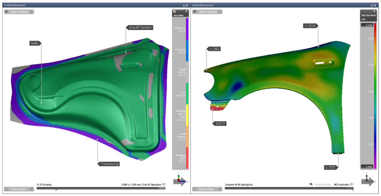
Figure 2: AutoForm results showing the stretched state of the sheet after drawing (left) and the elastic strain in the final part (right). In both cases, the finite element mesh is activated. [SC1]
However, the development of tools and the production of stamped parts and assemblies involves much more than just analyzing the behavior of the sheet metal under specific forming or assembly conditions. Over time, new features have been implemented in the program to allow the execution of all related tasks as quickly as the simulations themselves. Today, AutoForm includes modules dedicated to generating and quickly changing tool geometries, estimating tooling costs, compensating for springback, evaluating the influence of controllable and non-controllable variables on forming, and more. These features complement AutoForm’s FEM analysis capabilities, creating a comprehensive and integrated solution that guarantees maximum interactivity and efficiency for its users. The program even aids in managing stamped parts production lines with high efficiently.
Despite its vertical approach, AutoForm is commonly used not by experts in FEM, but by people with experience in defining processes and designing tools and devices. As such, the software is extremely versatile and easy to use, requiring just a few weeks of training to be used effectively. It is therefore up to AutoForm as a company to maintain a technical support team that also has experience in the field of sheet metal forming and assembly, capable of communicating with users in the same terms and concepts familiar in the industry. This team can provide advice not only on the FEM concepts used by the program, but also on the specific details of each manufacturing process. In this way, AutoForm has always been a trusted partner to its customers, working closely with the most important companies operating in the sheet metal forming and assembly sector worldwide.
AutoForm’s dedication to its specific segment, incorporating an efficient FEM simulator for analyzing the phenomena involved in sheet metal forming and assembly, alongside various auxiliary resources for part and process development, has resulted in an efficient vertical implementation that guarantees speed, accuracy, and ease of use. This combination has made AutoForm an indispensable tool in the development of stamped parts and assemblies.
Leandro G. Cardoso


