
Fenders have a very complex stamping process and share many matching elements with other BiW (Body in White) parts. Consequently, both dimensional accuracy and surface quality require careful attention. This article details how to achieve a high-quality fender using AutoForm analysis.
Basic Part & Check Fixture Information
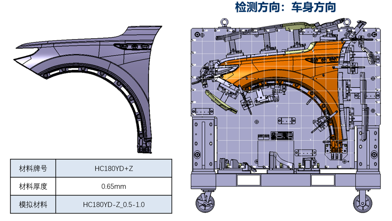
Fig. 1 Part design & measuring tool design
A five-operation (5-OP) stamping process—drawing, trimming, flanging, cam-flanging, and beak-restriking—is planned for this part:
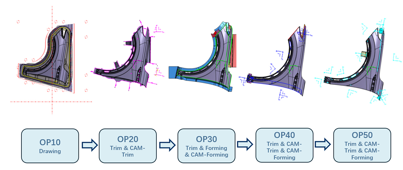
Fig. 2 Stamping process design
After validating the formability and robustness with AutoForm, we obtained the following springback results for each operation:
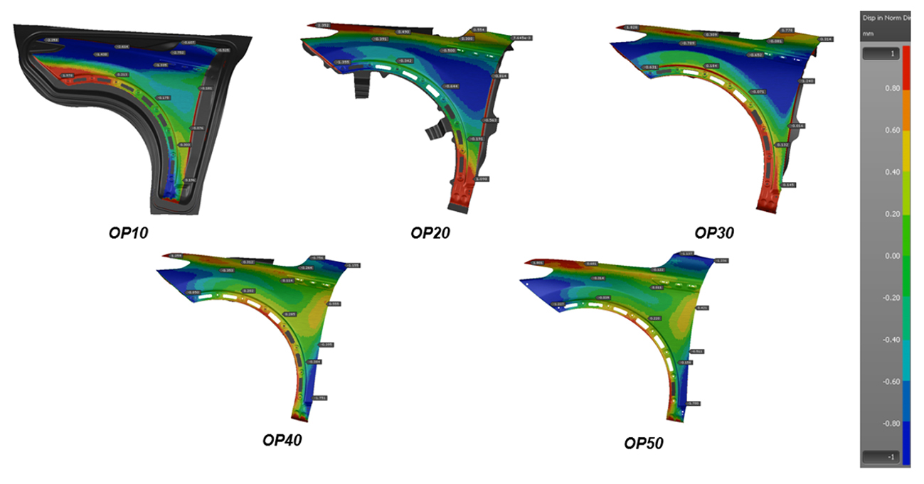
Fig. 3 Springback results by operation
It was apparent that in OP40 (cam restriking), the A-pillar area showed significant dimensional variation: the middle area was crowning upward while the two ends moved downward. The natural instinct might be to correct this issue with compensation; however, the best initial approach is to minimize springback through process improvements. This helps avoid the negative effects of excessive compensation.
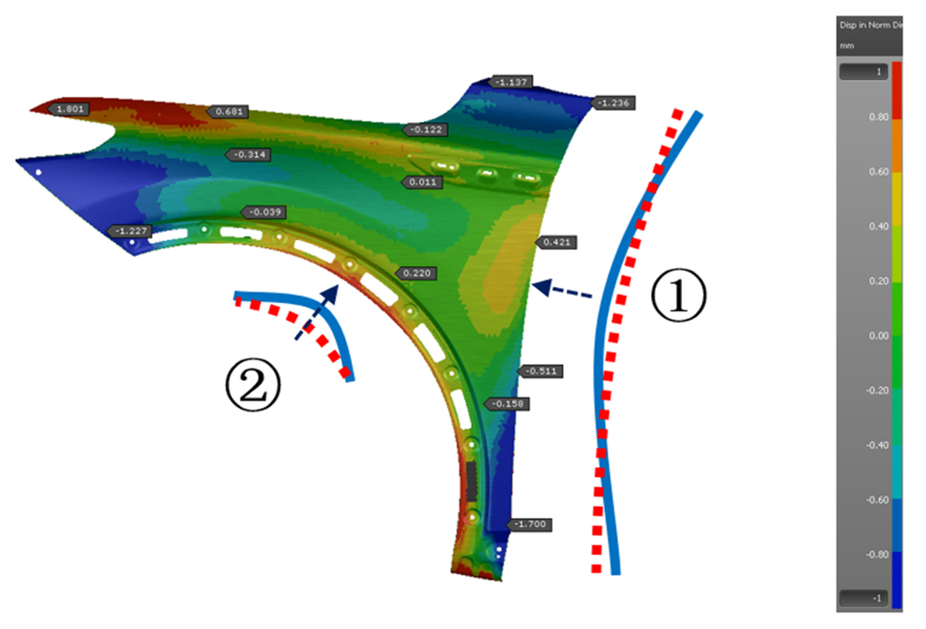
Fig. 4 Initial springback result
We observed poor dimensional accuracy in the A-pillar side and wheel-house area and attempted to improve them via:
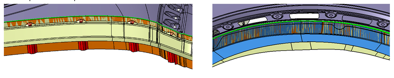
Fig. 5 Process adjustments
- Additional material gainer: This step relieves a large portion of material stretch during flanging in the A-pillar side, thereby reducing dimensional deviation.
- Adjust the flanging sequence: Re-design the flanging sequence in the wheel-house area.
After these adjustments, the springback in both areas was greatly reduced, and their dimensions fell within tolerance. Moreover, the overall distribution of springback improved, making subsequent compensation easier.
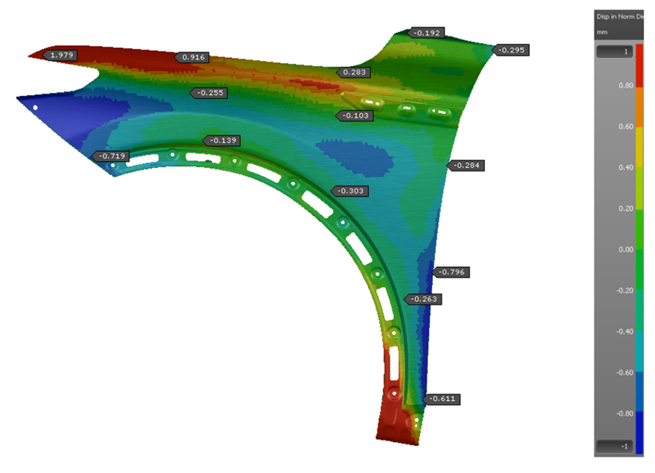
Fig. 6 Springback after process adjustments
Clamping Scenario Determination & Springback Assessment with Clamps
Clamping can significantly affect the panel’s dimensional accuracy. Poor clamping typically results in unrealistic springback data. After early-stage validation, we settled on the following clamping strategy:
The part was measured in the vehicle’s position and a Minimum Clamping Concept (MCC) was applied, with circles (○) indicating Reference Point System (RPS) clamping points and triangles (△) denoting pilot points. Two pilot points restrained the panel against gravity and limited its XY movement. Six clamps secured the panel in the Y direction.
In combination with the previously noted process adjustments, this strategy yielded the following springback results:
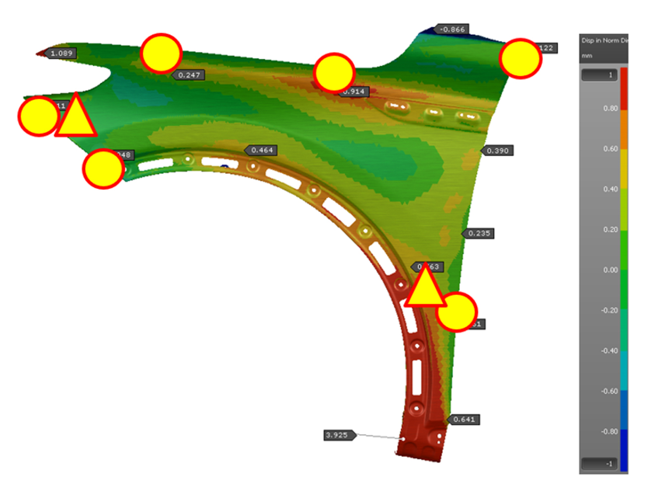
Fig.7 Springback results using the MCC strategy
We also validated the clamp and pilot force results. Excessive clamp force generally indicates panel distortion and leads to unreliable springback data. Here, each clamp’s normal force is under 5N, and the pilot load equals the panel’s weight, confirming the reliability of the simulation.
Compensation Strategy
Based on the springback results, we chose local compensation at the beak area (No. 2), the A-pillar (No. 3), and the dog-leg area (No. 1). We applied this compensation during OP10 through OP40, and in OP50 we used the nominal part surface (Fig. 8).
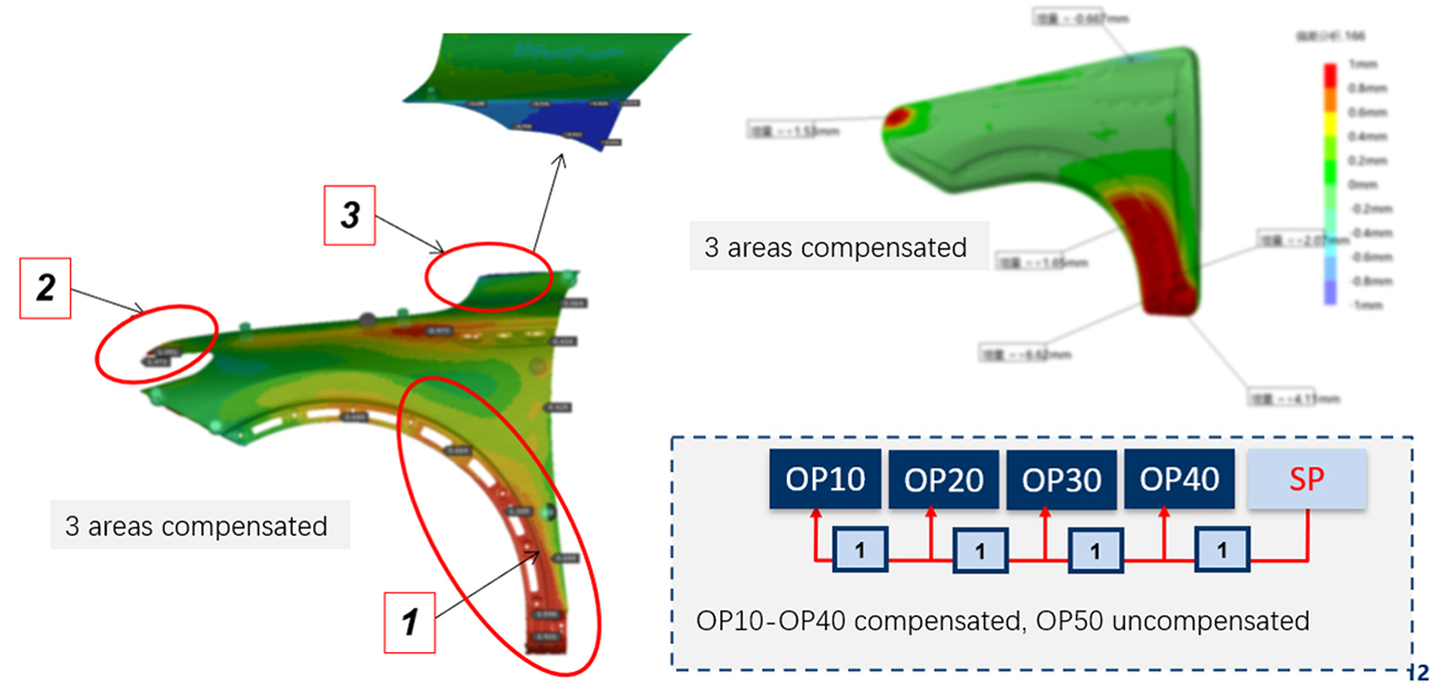
Fig. 8 Compensation strategy
Additionally, referencing AutoForm’s surface-low results and prior project experience, we expected potential surface quality issues in the framed section. To address this, we introduced local crowning compensation in that region.
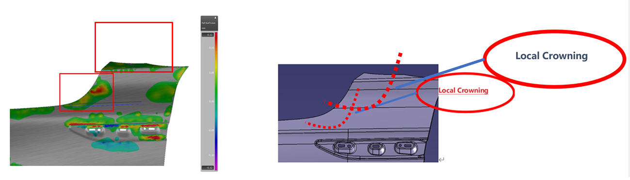
Fig. 9 Surface-low value reaches 0.1 mm Fig. 10 Local crowning compensation
After applying these strategies, the springback results improved under different clamping methods:
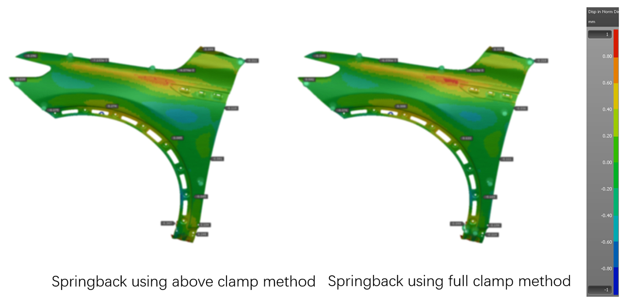
Fig. 11 Springback under two different clamping methods
Finally, the tryout panel achieved high quality, with 91.3% of measuring points within required tolerance. The simulation and actual results showed close correlation, with less than a 0.5 mm difference.
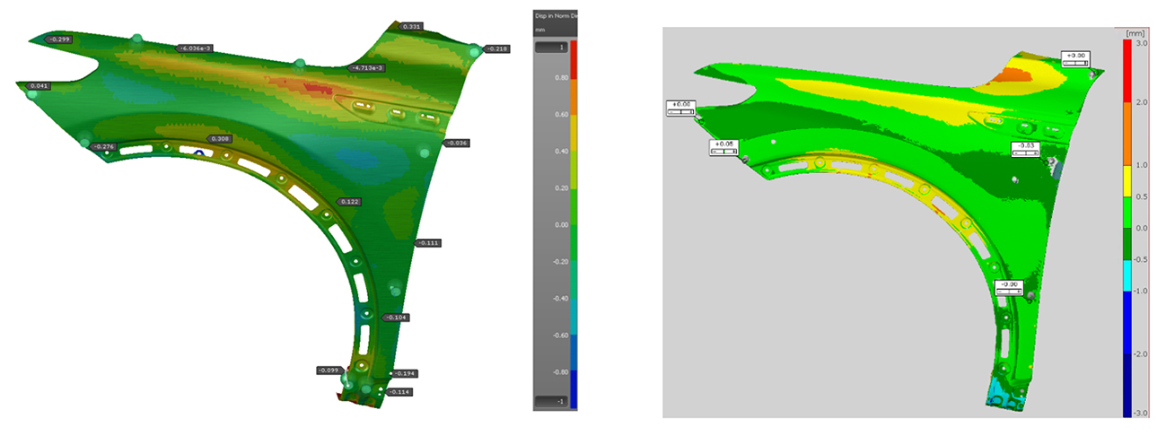
Fig. 12 AutoForm theoretical results vs. tryout scanning results
Furthermore, the tryout engineer reported that the panel’s surface quality is noticeably better than in previous projects, reducing spotting time. As shown below, the real panel’s surface defect is less than 0.02 mm.
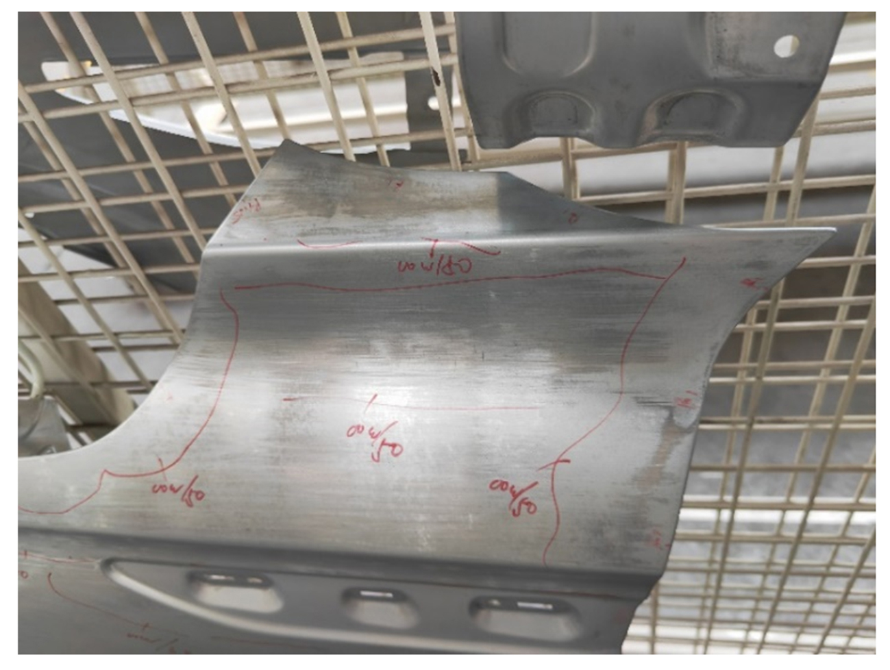
Real panel with minimal surface defect
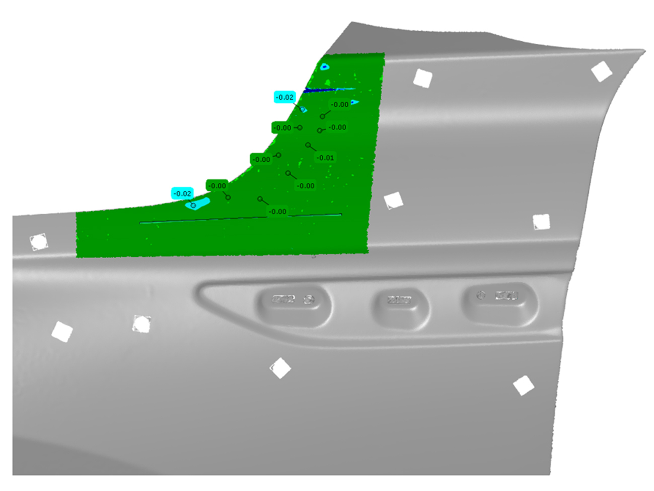
Analysis of scanning results showing a less than 0.02 mm defect
Conclusion:
- High-quality compensation can be achieved through AutoForm analysis.
- A suitable process strategy is essential for minimizing springback.
- A robust clamping strategy is crucial for ensuring realistic dimensional outcomes.
- Finally, translating the engineering process intent into actual tool manufacturing and tryout helps align real outcomes with the digital plan, providing better correlation.


?")


