
Press Die Process Analyzed at SAIC General Motors China
Forming World recently received several highly welcomed blog posts from Chinese tool makers & OEMs, which will be published accordingly in the following months. In this blog post read how Mr. Zhang Bofan and Wang Zengqiang from SAIC General Motors used AutoForm’s sensitivity study to save a decklid inner panel from cracking:
Introduction
Automotive covering parts are large in size, complex in shape and mostly free-form in space. The forming process involves geometric nonlinearity, material nonlinearity and contact nonlinearity[1,2]. There are many influencing factors and it is difficult to determine the source of issues accurately.
With the development of CAE technology, we’ve seen a wide application of simulation technology of stamping forming, which serves to optimize the stamping process and die design methods, making it possible to predict the forming defects of parts in the early stages of die design and improve the efficiency of die design itself[3]. However, due to the limitation of equipment and production requirements, the die needs to be corrected in the factory. In the tryout process, we mainly rely on the experience of die makers, so the quality and progress of the die tryout are difficult to ensure.
In this case, when decklid inner panel die was in the tryout stage at the factory, many parts saw splits and it seemed difficult to find a solution, even after several correction loops. Seeing there are so many factors that affect splits (drawbeads, location, thickness, blank holder force, lubrication[4,5]), and considering these factors affect each other, it takes a lot of time to correct, thus negatively affecting project timing.
We decided to test AutoForm-Sigma and its module in a virtual tryout. This particular module can be used to find the chief factors that cause splits for a part and solve problems when practically applied.
Sigma Module Application Case
The decklid inner panel split during the die tryout process, which was difficult to solve in time.
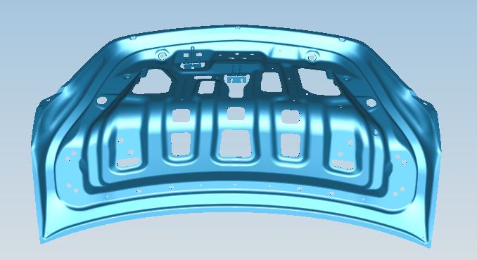
Fig. 1: Decklid inner panel
No splits and other defects were identified in the early simulations. However, due to robustness failure in the early stage, hidden defects occurred in the part during the field tryout (figure 2 and 3). A risk for splits could be seen in the part. With so many factors that affect splits in need of analysis, such as drawbead resistance, sheet position, thickness, blank holder force, lubrication, material parameters, etc., we needed to develop a variety of approaches for correction during a tryout. Seeing that the field tryout needed spotting for the die, not only was it time consuming but it also had an impact on the precision of the die.
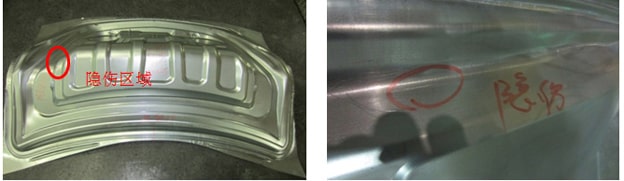
Fig. 2: (left) Tryout sample. Fig. 3: (right) Hidden injury area of parts
The AutoForm module itself functions through an integral analysis of various factors affecting the product defects, according to statistical rules. The probability of product failure under these factors is calculated to find out the chief factors, and can then calculate the defect rate under the quality standard. Therefore, the AutoForm module was used to analyze the main causes of product failure and the solution was determined quickly.
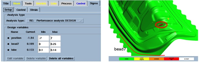
Fig. 4: (left) Parameter setting. Fig. 5: (right) Risk area.
Three chief factors leading to the splits of the hidden injury area of the parts were selected: the plate position, the drawbead restraining coefficient and the lubrication coefficient. The position tolerance is ±7mm, the drawbead restraining coefficient is 0~0.25, and the lubrication coefficient is 0.1~0.14, as shown in Figure 4. The AutoForm module performs a combined calculation of the fluctuation range of these three parameters. The results are shown in Figure 5.
Figure 6 shows the extent in which three key factors affect the part splits. As seen in figure 6, the influence ratio of lubrication coefficient on the part splits is about 80%, the influence ratio of drawbeads is about 18% and the deviation of plate positioning has little influence. It can be confirmed that the parts split mainly from the lubrication coefficient, and therefore consider reducing the size of the drawbeads.
Figure 7 is the diagram of lubrication influence coefficient on the part splits. The horizontal axis represents the value of lubrication coefficient. The ordinate represents the maximum failure value. It can be seen from figure 7 that the lubrication influence coefficient on the splits shows a linear behavior, that is, the smaller the lubrication coefficient is, the lower the risk of splits.
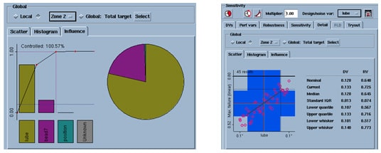
Fig. 6: (left) The influence of various parameters on splits. Fig. 7: (right) Lubrication coefficient affects the law.
According to the above analysis, we saw two proposals that would solve the splits issue: (1) reduce the lubrication coefficient, that is, to increase the amount of lubricant on the sheet, or the main parts of the die (punch, die, blank holder) chrome plating; or (2) reduce the drawbead resistance in this area where the parts are formed.
Through software analysis, the chief factor of the part splits was found quickly, and the solution to the problem was suggested. Targeted measures were taken according to the proposed solution during the die’s tryout on site. At present, the hidden injury of this part has been solved successfully. Qualified parts are shown in figure 8.
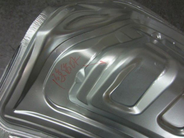
Fig. 8: Qualified part
Conclusion
As a result, the two following conclusions were drawn:
(1) The virtual forming module in AutoForm was used to analyze the chief factors affecting the part splits, determine the main factors, guide the field tryout and solve the issues in time. This method is of great significance to shorten die correction loops, reduce trial costs and improve production efficiency.
(2) An additional robustness window is provided in Autoform to analyze the stability of the part forming process. For the parameters affecting the process, a certain fluctuation range is set according to the field conditions. The robustness feature is used to calculate whether the process is stable or not within the fluctuation range. Through the robustness analysis, it can not only improve the efficiency of tryout, but also ensure that parts formed in actual production will not be interrupted by the fluctuation of working conditions, and maintain the continuity of production.
Mr. Zhang Bofan, Wang Zengqiang
Mr. Zhang Bofan works at SAIC General Motors Corporation Limited as an engineer focusing on SE for earlier stage car development. SGM, a joint venture of SAIC group and General Motors, founded in 1997, is now a leading company in China’s automotive industry.
Further Reading:
[1] Hu shiguang, Chen hezheng. Engineering analysis of sheet cold stamping [M].Beijing: Beijing University of Aeronautics and Astronautics press, 2004:16-28.
[2] Wei yiping, Wang jian, Lei junxiang. Simulation of stamping die for automobile covering parts [J]. Die & Mould Industry,2005,(10):3-5.
[3] Tang guoxing, Zhou fang, Lou xinyong. Cause of formation and elimination of surface impact line of decklid panel [J].Die & Mould Industry,2012,38(7):44-46.
[4] Xiao jingrong, Jiang kuihua. Stamping technology [M].Beijing: China Machine Press,1999:151-171.


?")


