
FluidForming Americas, LLC, headquartered in Hartsville, Tennessee, provides engineering, consulting, rapid prototyping, and small-run production services. The FluidForming metal forming process enables the manufacturing of highly complex parts for customers in the aerospace, commercial product, energy, and automotive sectors.
Recently, FluidForming Americas collaborated with a defense contractor that supports the U.S. military in addressing issues of obsolescence. In this case, the objective was to recreate a highly complex part for the U.S. Air Force.
Engineering a Replacement Part for the U.S. Air Force
The FluidForming hydroforming process employs the highest forming pressures in the metal forming industry—up to 60,000 psi—to achieve exceptional part accuracy and repeatability, making it an ideal solution for this demanding project. (See this instructive video for an introduction to the process and its benefits.)
To recreate the Air Force part, the engineering team at FluidForming Americas used AutoForm to iterate and optimize the tool design, achieving a virtually stress-free, highly accurate component. The primary challenge was forming a narrow channel within a complex geometry that featured significant draw depth.
FluidForming Product Development and Optimization Process
Working closely with the contractor’s team, FluidForming Americas was able to recreate the part and refine the tool design to achieve a virtually springback-free component.
The company employs a careful product development and optimization process to ensure part accuracy and repeatability. Once CAD files are received and a purchase order is confirmed, the process begins with a one- to three-week value engineering analysis in collaboration with the customer. This phase involves iterative simulations to accommodate any necessary design changes, ensuring a cost-effective and manufacturable solution.
Starting from a 3D CAD drawing supplied by the contractor, the team created a simulation tool surface to assess feasibility and potential forming challenges.
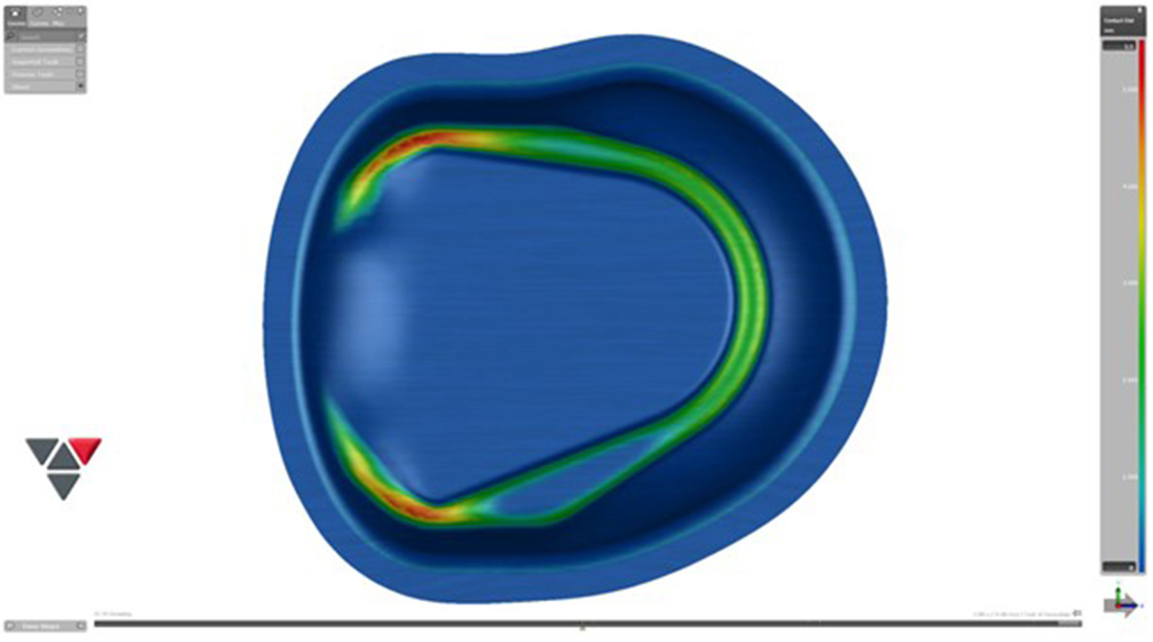
Fig. 1: First simulation (contact distance)
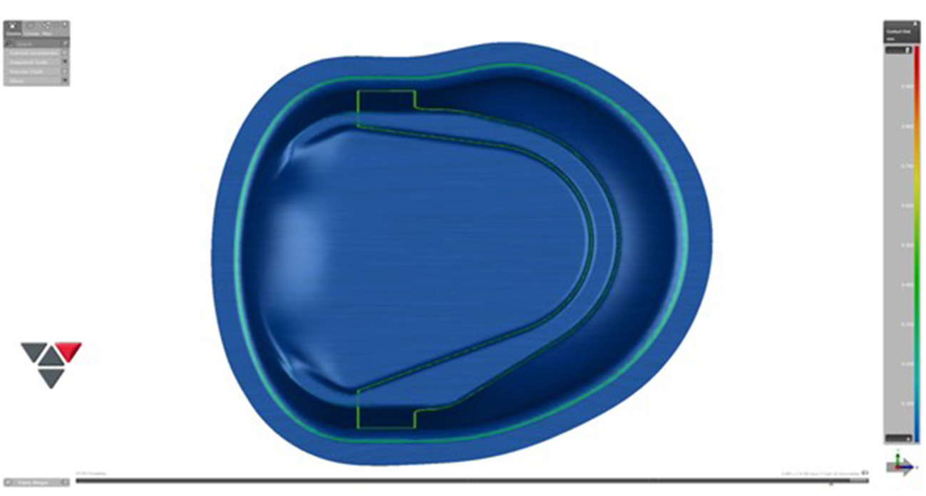
Fig. 2: The final simulation of the re-engineered part produced collaboratively by the defense contractor and FluidForming Americas for the U.S. Air Force (contact distance)
Iterating through various process alternatives in simulation revealed that forming the part would work best using multiple forming steps (with the same tool) and intermediate annealing steps. Simulation confirmed that this approach would produce a part free from significant springback, ready for downstream operations and installation.
During the second phase, which typically takes four to eight weeks, the tooling is created. Once complete, initial setup for approval parts and production begins. This is typically achieved in under three weeks; however, complex parts requiring intermediate annealing—such as this Air Force component—may take longer.
Once part approval is granted, production begins within one to three weeks, depending on material availability and scheduling.
Precision and Material Flexibility
Every step of the FluidForming process, from material flow to clamping pressure to water volume and forming pressure, is precisely controlled. Forming pressures of up to 4,000 bar (60,000 psi) enable finer, more detailed results than any other metal forming process available today. Material thicknesses range from as thin as 0.0008” to as thick as 0.3”, enabling the production of components from membranes to pump housings and pressure vessels.
Material selection is virtually unlimited and is only constrained by material properties, not machine or process limitations. FluidForming Americas has successfully formed parts from titanium, Inconel, Hastelloy, stainless steel, aluminum, and both cold- and hot-rolled draw steels.
Furthermore, FluidForming hydroforming requires just one tool, dramatically reducing costs and production time. The FluidForming FormBalancer can accommodate 3D-printed tooling and a range of mold materials including aluminum, hot-rolled steel, and tool steels. The ability to use modular tooling and inserts offers additional flexibility and cost efficiency when forming complex parts.
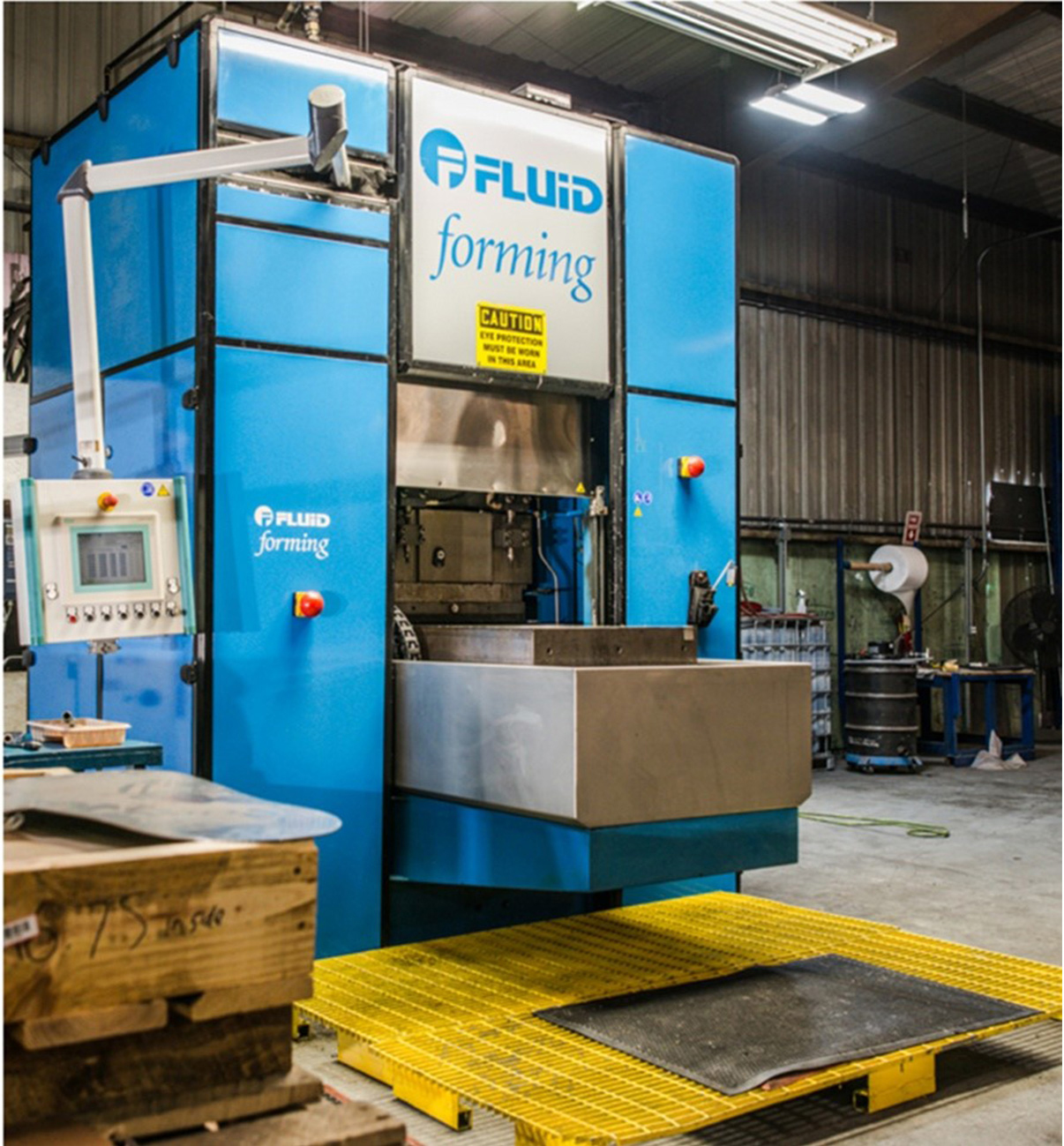
Fig. 3: The FluidForming FormBalancer FB25
Time and Cost-Saving Benefits of Simulation
Simulation enabled the FluidForming Americas engineering team to conduct an initial review of the part, determining formability and material thickness early in the process. This allowed them to provide valuable feedback and recommendations before tooling was made.
Initially, the part was slated for a single forming step. However, the value engineering analysis revealed that the required depth and narrow profile at the bottom would cause material ripping. Instead, a three-step forming process using a single tool with intermediate annealing was adopted, ensuring a successful and repeatable outcome.
This innovative solution resulted in acceptable material thinning in the critical areas, no tearing, and virtually no springback after trimming. The forming pressures required were 40 MPa (5,800 psi), 100 MPa (14,500 psi) and 200 MPa (29,000 psi) for the first, second, and third forming steps, respectively. Formed from stainless steel, the material thickness was maintained at approximately 0.095″ in key regions, starting from 1.27″ and resulting in about 25% total thinning.
Projected springback ranged from -0.27 mm to +0.48 mm, with critical areas showing only about ±0.2 mm.
AutoForm allowed both teams to identify and address potential issues before manufacturing a tool or forming a single part, saving significant time and costs.
For more information about FluidForming Americas’ services, metal forming processes, and additional case studies, visit their website here. FluidForming Americas, LLC is a member of the Precision Metal Forming Association and is AS9100 Rev D, ISO 9001:2015 certified, as well as ITAR registered.


?")

 Process: Hot Forming Challenges Part 2")
