
Introduction
During the heating and cooling treatments involved in coating electrophoresis or post-painting baking, the body side outer panel of a Body in White (BiW) may suffer permanent plastic deformations such as buckles or waves. These defects significantly impact the quality of the vehicle. Typically, these deformations arise due to:
- Local temperature differences between the side outer panel and the inner panels during the heating-cooling cycle, which can cause uneven deformations and leave defects on the surface of the outer skin panel after cooling.
- The differing thermal expansion coefficient of steel and aluminum in hybrid BiW structures, which can cause localized plastic strain on the surface of the steel side outer panel during the heating-cooling cycle.
In a steel-aluminum hybrid BiW, both issues may exist simultaneously, and compared to structures made entirely of steel or aluminum, these problems are more frequent. Addressing these issues in tryout or production involves extensive validation countermeasures across departments and is highly inefficient.
However, these issues can be effectively avoided if identified and verified at the initial product development stage using CAE simulation tools. This proactive approach significantly reduces the likelihood and severity of such problems during manufacturing.
This article introduces the application of AutoForm-Assembly Thermal-Curing module in analyzing and preventing these issues.
Analyzing Baking Distortion with AutoForm-Assembly Thermal-Curing Module
In the simulation, several key physical parameters critically influence the results and must be accurately set and defined in the material card:
- Thermal expansion coefficient is the most influential parameter in the electrophoretic baking simulation with AutoForm-Assembly.
- Thermal conductivity indicates the material’s heat conduction difficulty.
- Convective heat transfer coefficient reflects the heat transfer capacity between the fluid and the solid surface. It must be defined for the simulated object and the environment during the electrophoretic baking simulation stage.
Pre-Processing Steps
Several steps are required during pre-processing.
First, parameters such as material thickness direction, material thickness, material physical model, and thermodynamic parameters are set. The imported subassembly in this scenario is shown in Figure 1.
In the process planning stage, the number of operations is established, along with which part/subassembly is assembled in each operation, resulting in an assembly sequence tree shown in Figure 2.
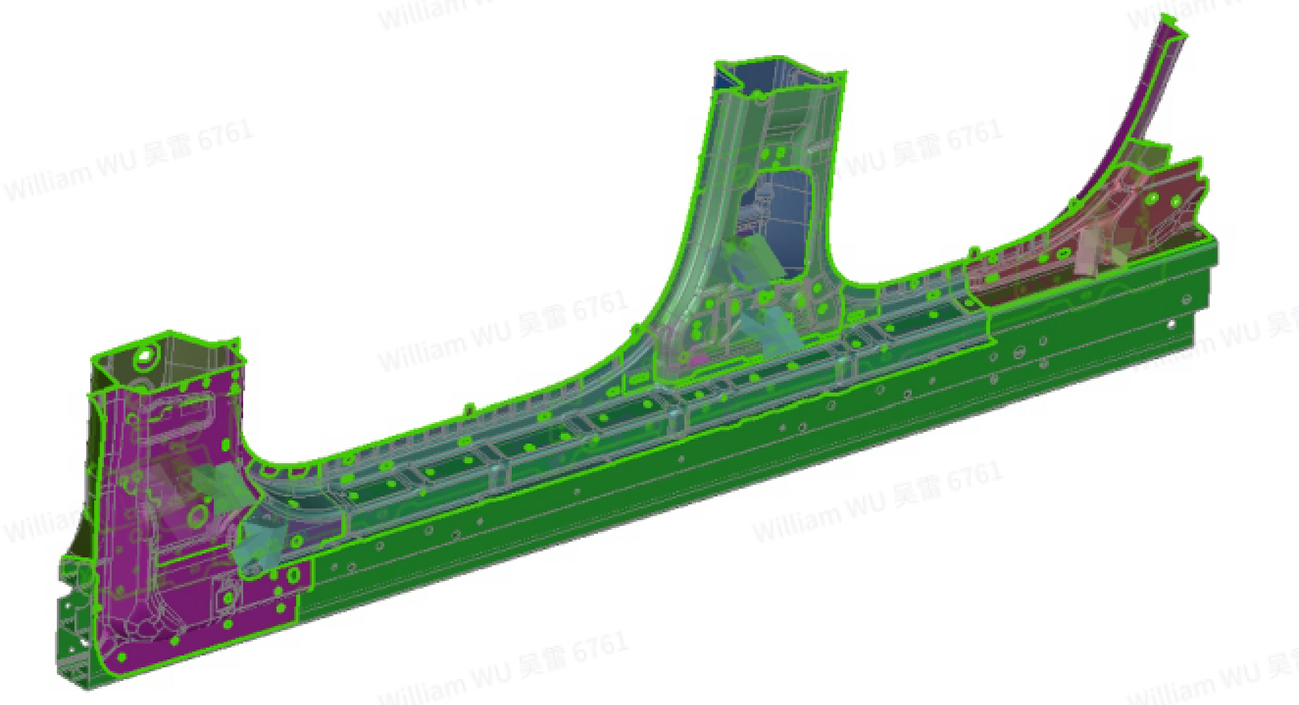
Figure 1: Subassembly imported to AutoForm-Assembly
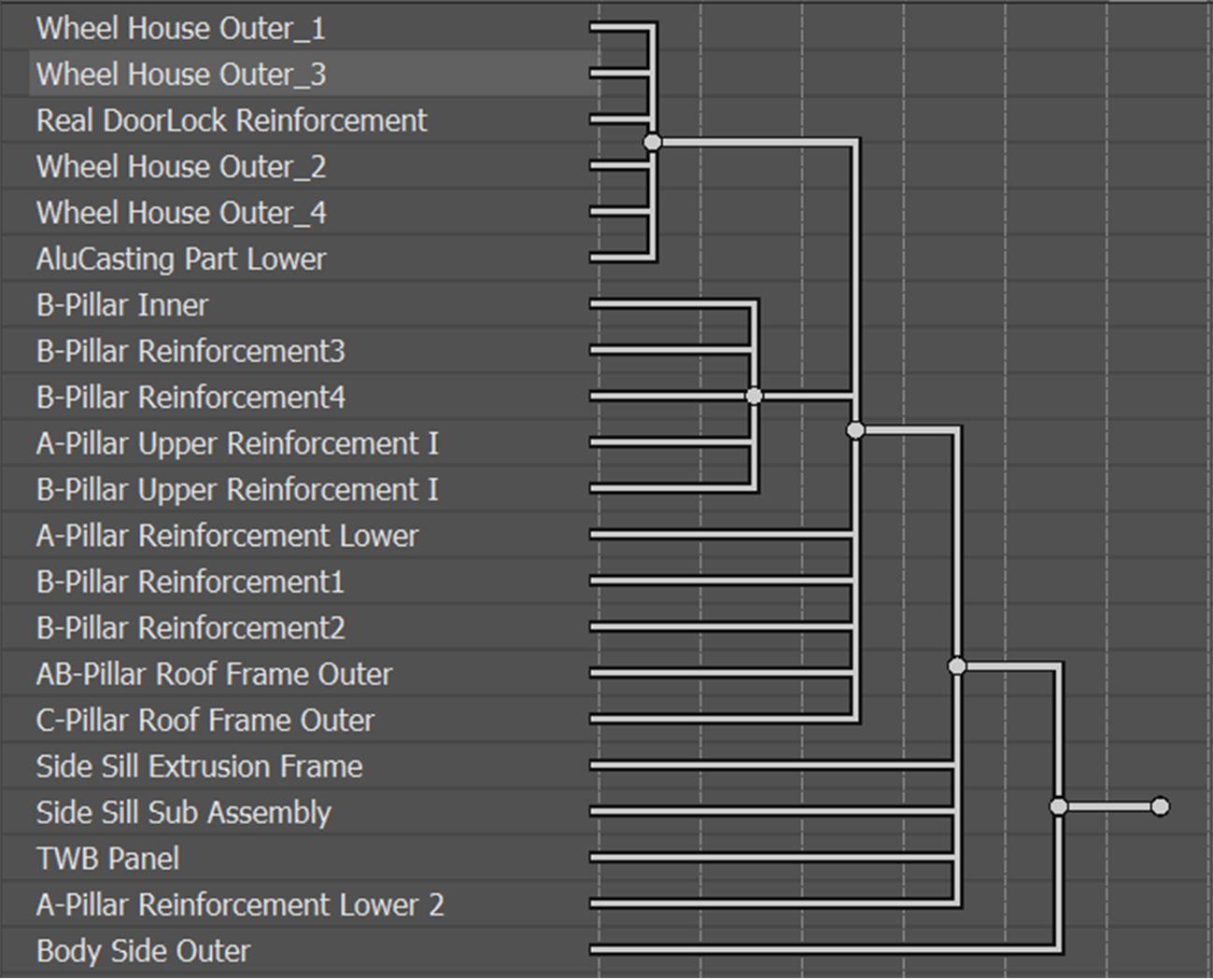
Figure 2: Assembly sequence tree
During loading and fixation, for each operation, it’s necessary to establish the loading sequence (Figure 3), loading direction, positioning, and clamping strategy to ensure the stability of each part/subassembly during joining.
Next is joining and gluing; spot welding, bonding (Figure 4), and Flow Drilling Screw (FDS) are used in our case. Since FDS is not yet integrated into the software, rivets are used as a substitute model.
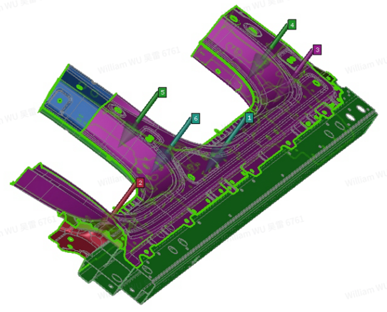
Figure 3: Loading sequence
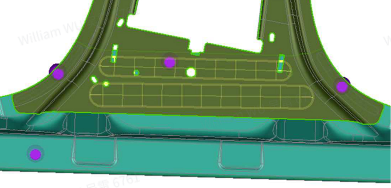
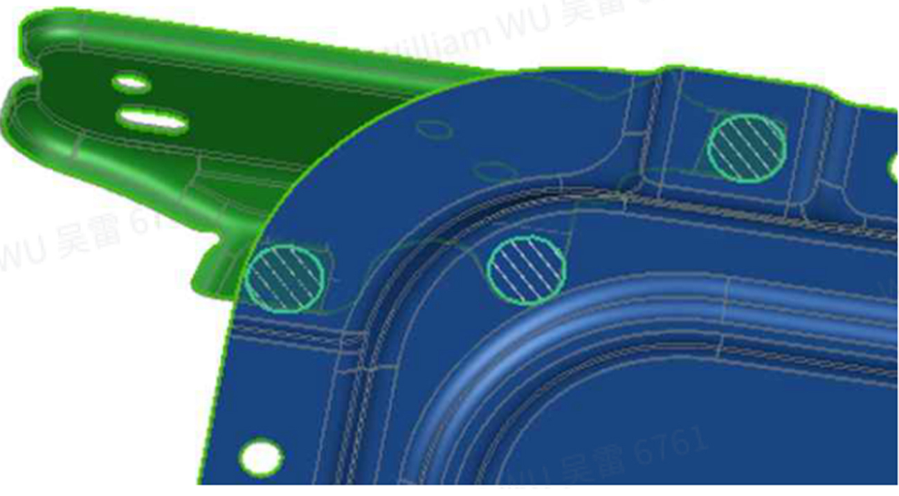
Figure 4: Glues used in simulation
Finally, in the simulation, the thermodynamic parameters (thermal expansion coefficient, thermal conductivity coefficient and convective heat transfer coefficient) are defined for each part and material. The heat transfer coefficients are set at 45mW/mmk for steel, 220mW/mmk for cast aluminum, and 23.3mW/mmk for hot-formed steel. The convective heat transfer coefficient between the body and the environment is set at 0.02 mW/(mm^2·K). Additionally, the heating and temperature holding times during baking are configured to align with real process condition.
Interpretation of the Simulation Results
The quality of the simulation results for side panel deformation is primarily determined by the extent of deformation and the virtual oil stone performance, as illustrated in Figure 5.
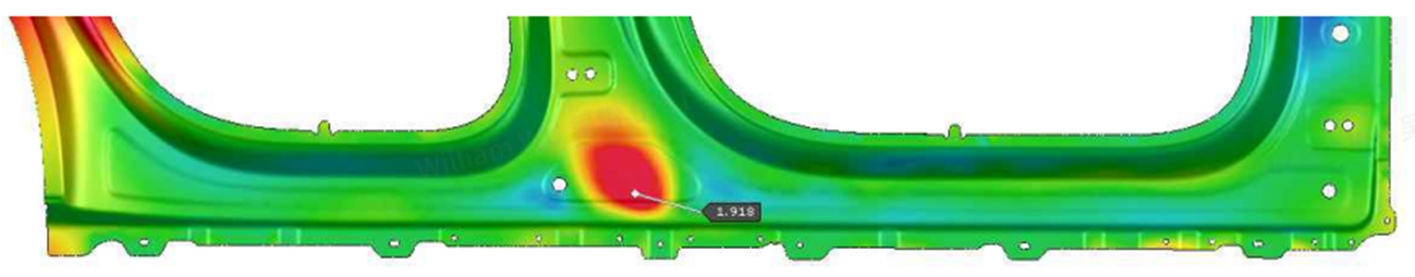
Figure 5: Deformation of side outer panel
The significant bulging of 1.9mm in the lower area of the side outer panel is due to the aluminum extrusion beam’s higher thermal expansion coefficient compared to the other steel panels (see Figure 6). This deformation is generated during the heating-cooling cycle. If the value of this plastic deformation shows a gradient change, with no abrupt variations in the local area, then the surface defect can hardly be detected in the actual vehicle. Consequently, this variable serves as an indicator of structural stiffness, which can be used to optimize stiffness during preliminary structural design.
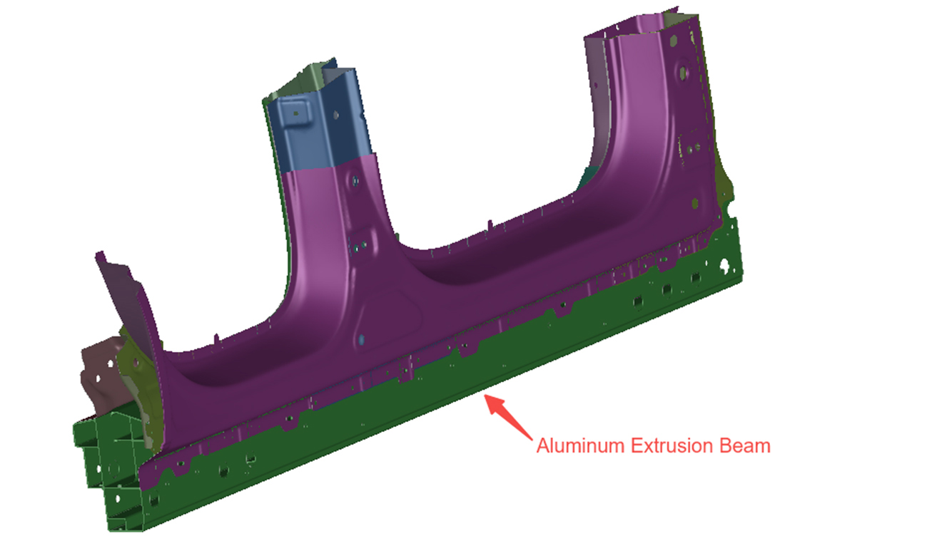
Figure 6: Aluminum extrusion beam of body side assembly
Figure 7 shows the virtual oil stone results. An abrupt value of max. 0.17mm was observed on both sides of the lower end of B-pillar area. Combining these results, we can conclude that waves are generated in this area.
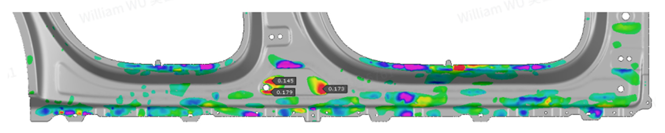
Figure 7: Virtual stoning results along X direction
The results shown in Figure 7 typically indicate potential surface defects such as pits or waves under physical conditions. Thus, this output is used to evaluate the final indicator of surface quality affected by baking deformation.
Validation of the Simulation Results
Figures 8 and 9 compare the actual outer panel before and after electrophoresis, highlighting the deformation trends and their correlation with the simulated results.
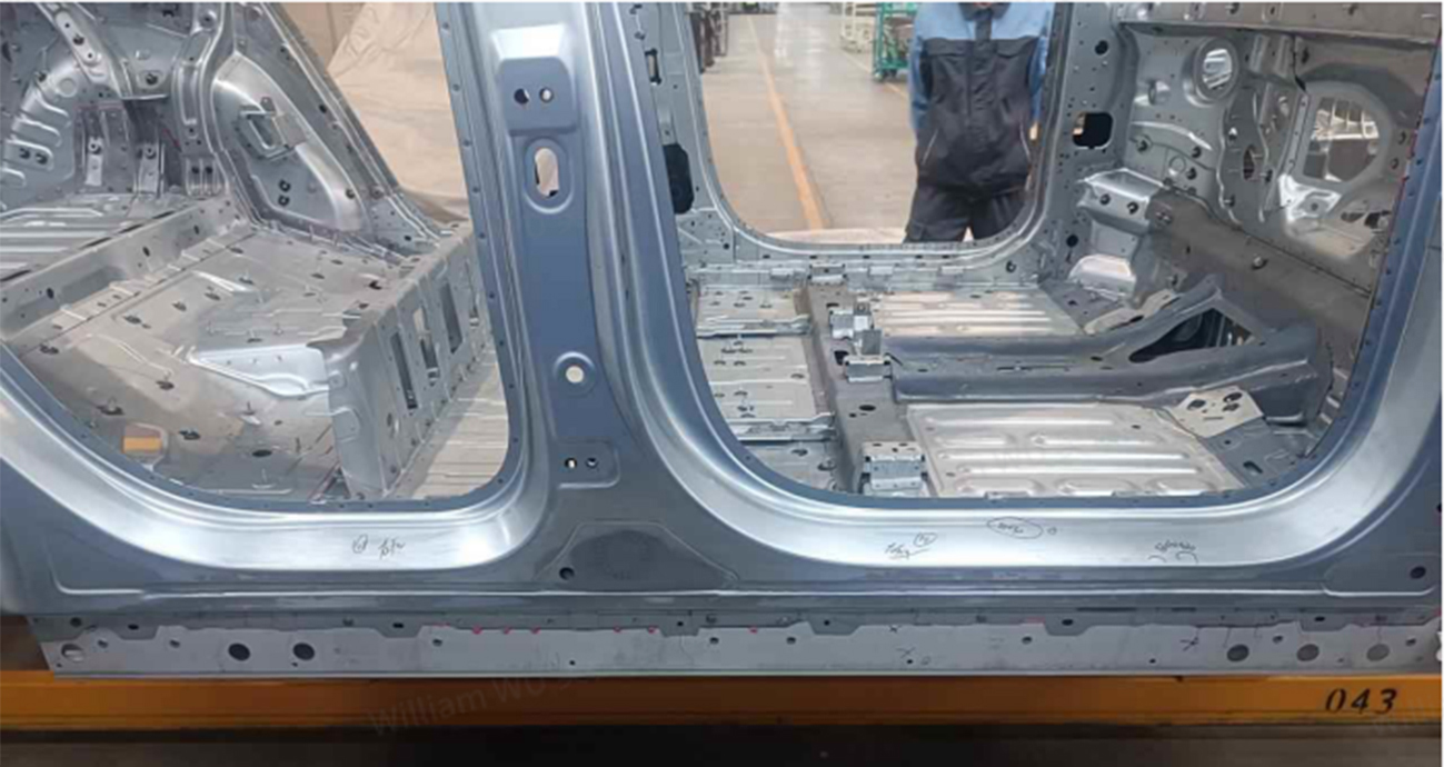
Figure 8: BiW before electrophoresis & baking
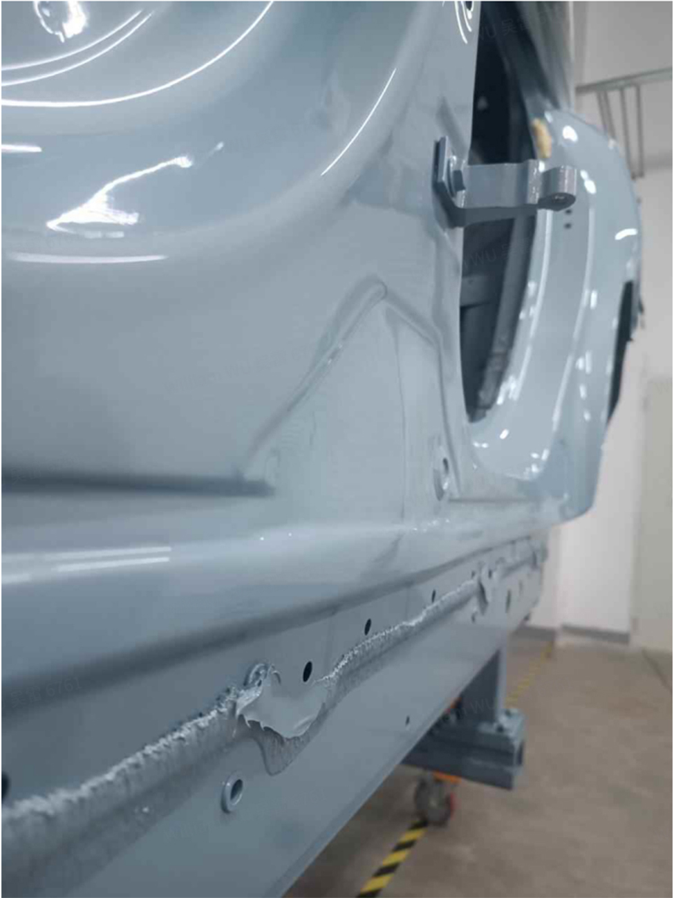
Figure 9: State after electrophoresis & baking
The bulging deformation is easily detectable at the lower end of the B-pillar area, matching the trends shown in Figure 5.
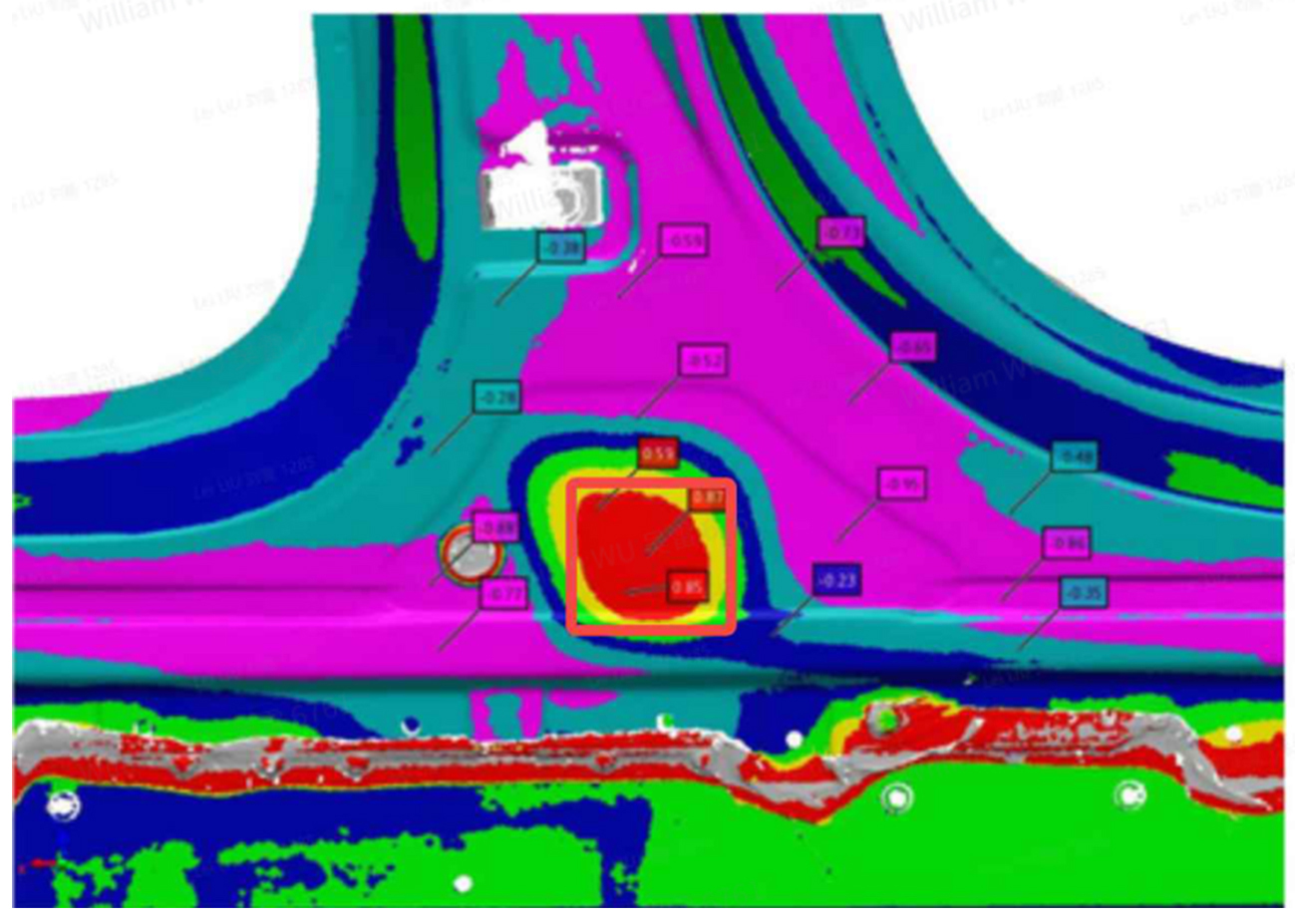
Figure 10: Scanned result of B-pillar area after electrophoresis
Figure 10 shows the scanned results of the B-pillar area’s deviation from the nominal design after electrophoresis. Compared with Figure 5, the bulging deformation shows a high correlation with the simulation results both in trend and distribution, indicating considerable accuracy in the assembly simulation of baking deformation.
Conclusion
The issue of side panel baking deformation has long been a challenge within the automotive industry. Due to limitations in analysis tools, it has been difficult to effectively evaluate the influence of structural stiffness design on mitigating this issue. Traditionally, the solution has involved adding extra reinforcing patches, which not only decrease efficiency, but also increase costs. However, the adoption of Thermal-Curing technology now allows for a precise evaluation of baking deformation of the side panel, enabling the effective improvement of structural design. This approach significantly reduces the risks associated with this problem during vehicle manufacturing and reduces the cost of using extra patches.
Additionally, this type of analysis can also be applied to other sub-assemblies, such as doors with different material types, further extending the potential benefits.
Testimonial from NIO
Mr. Tu, Head of the Digital Simulation Team, emphasizes the broader relevance of these issues: “Many other companies face similar baking deformation issues in hybrid BiW; it is highly recommended to use AutoForm Assembly to do early analysis and to reduce potential losses in the tryout and production stages!”
About the authors:
Xiaowen Tu heads the Digital Simulation Technology Team and is an expert in the stamping process at NIO’s Foresight Manufacturing Engineering Department, bringing 22 years of experience in the automotive industry with proficiency in numerical simulation technology.
Pengpeng Liu Xiaoqian Pan is an integral member of the NIO-Foresight Manufacturing Process Innovation Center Team.
JuLei Wu Lei Liu is a key representative of the NIO-Manufacturing Engineering (BiW System) Department. On behalf of our fans at FormingWorld.com, thank you for this excellent case study.
Thanks also to Xu Jian & Shadow Lu from AutoForm for organizing this post.


?")


