
Emrah Bayrak from AutoForm Demonstrates How to Resolve ProgDie Forming Issues Using AutoForm
In this post Emrah Bayrak, Technical Product Manager at AutoForm, demonstrates some key functionalities for advanced feasibility analyses of progressive die forming processes. He focuses on the examination, identification and resolution of forming problems using AutoForm’s unique functionalities for ProgDie processes. In addition he gives us an over-the-shoulder-view on how to examine advanced tool kinematics and how to optimize trim lines for ProgDie parts. The part under examination is a real automotive part in production using a ‘two step drawing process.’
In starting the feasibility analysis we evaluate the forming process using a single drawing operation. The first few operation steps in ProgDie processes usually involve some blanking cuts in order to shape the blank for the parts and the strip required for part transport inside the press. Using a single draw after blanking the simulation result shows heavy wrinkling in the curved flange area.
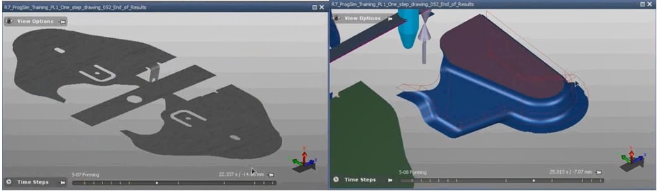
Fig 1: (left) Strip after initial blanking operations,
(right) part formed in a single operation.
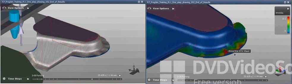
Fig 2: Wrinkles appear on the flange due to excessive compressive stress.
The wrinkling problem may be reduced by including a second forming operation. In this case, instead of using one single forming operation the part shape is drawn only half way in the first step and is finished in the second forming step. The blank/strip shape is the same but the simulation shows that the forming process this time does not cause any wrinkles.
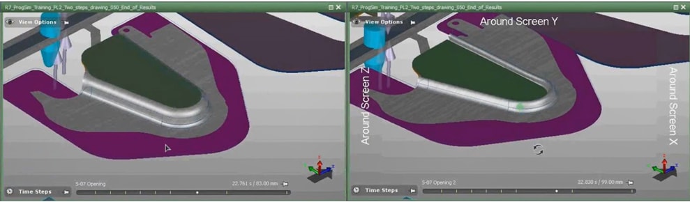
Fig 3: (left) part formed half way, (right) the part is destroyed during tool opening.
The simulation of this two-step drawing process also shows that the tool kinematics need to be set up very carefully or the part may actually undergo a reverse-draw once the tools are opened. The simulation gives you valuable guidance on how the various tooling components need to be opened after the draw in order to obtain the desired forming result – long before the physical part tryout is to take place.
AutoForm’s “Accurate Tool Opening” feature allows us to precisely configure which tools are opened in which order. In the case of this part, the simulation showed that if you open all of the tools at the same time the tools would destroy the sheet. Yet it demonstrated that if you open the tools separately, in the proper sequence and with proper delays between the various tooling components, the part will remain intact.
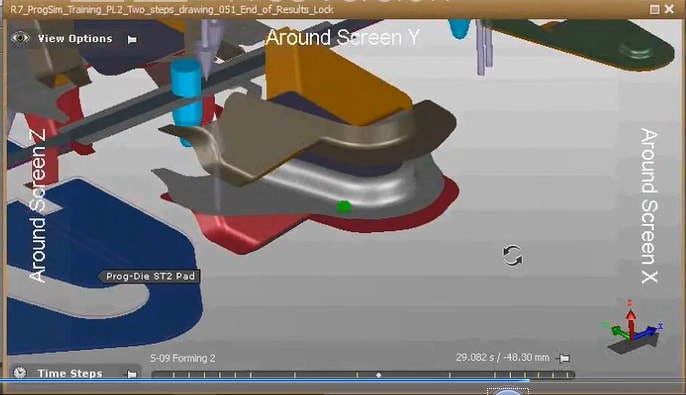
Fig 4: Second forming operation for completing the final shape.
Now that you have fixed your wrinkling problems and your tool opening issues we can closely examine the sheet in the second forming step to complete the feasibility analysis. In the first step we only formed the part half way, now we complete the forming process, drawing down the remaining part of the flange. The final shape is the same as when using a single operation – but now we can successfully achieve the desired part shape without any wrinkles, which would have occurred if using a single forming step.
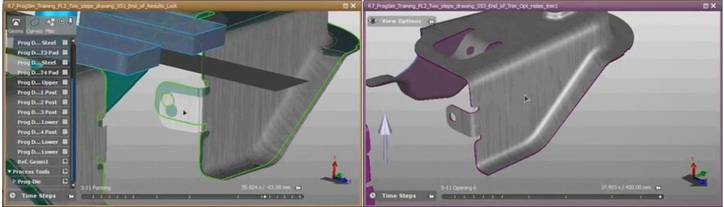
Fig 5: (left) trim line issues, (right) final part with a perfect trim line.
Towards the end you may end up with several trim line issues, where the outside contour of the part does not meet the desired part shape indicated by the trim lines shown in green. We can optimize this automatically to correct where the initial blank was cut so that – at the end of the forming process, the outer part contour is congruent with the desired trim line target. Since this process involves a few iterations in the software, this process is called a ‘trim line optimization’. However, since this iteration process digitally takes place, the optimal blank trim line may be found in a much shorter time span (and much cheaper) than the iterative optimization process using the actual forming and blanking tools.
‘The process of optimization is not about a single best approach. It’s a path you need to follow to find the best working approach for you. In the course of optimization you can change the process layout, the kinematics of the tools, the pressure applied etc. Everything you can change in reality for process optimization can be changed within the software.’ Emrah Bayrak, AutoForm Tech Services in the Netherlands.
About Emrah: Emrah Bayrak is the Technical Product Manager for Progressive Dies and Trim Optimization at AutoForm. He has worked at AutoForm for four years, previously having worked at Ford Motor Company as a Die Process Engineer.
Don’t forget new fans, subscribe to our blog! You’ll get one email once per month on the top latest posts & zero marketing messages.


?")


