Presented by Fagor Arrasate, Spain.
The weight reduction of vehicle parts has been a key priority for meeting the demand of reducing fuel consumption and thus environmental pollution. While components made from hot stamped steels are the material of choice as strategic safety automotive components, 6xxx and 7xxx aluminum alloys are emerging due to their high specific strength and low density. Despite their lightweighting potential, they are more challenging to form than steels. For that reason, one of the promising alternatives to improve the formability of these aluminum alloys is to increase the forming temperature via hot stamping. The forming step must be then performed somewhere within the thermal cycle of the heat treatable aluminum alloys, which typically consist of a Solution Heat Treatment (SHT), Quenching and Age hardening (Figure 1). The forming is usually combined with the quenching step inside the forming die all at once, using chilled tooling.

Figure 1: Complete thermal cycle of heat treatable aluminum alloys.
Unfortunately, nowadays there is no sufficient knowledge for a reliable process development of aluminum hot forming as it deals with a widespread variety of brand new issues. For that reason, Mondragon Unibertsitatea (as knowledge provider), Fagor Arrasate S. Coop. (Hot Stamping line supplier) and Batz S. Coop (Tool manufacturer) teamed up to perform semi-industrial trials on hot stamping of a real car bumper component using high strength aluminum alloys. These has allowed us understanding the role of different process parameters, obtain the rules for a reliable tool design for this technology and to define the lay-outs of different aluminum hot stamping lines that fulfil our customers specifications.
Use Cases & Facilities
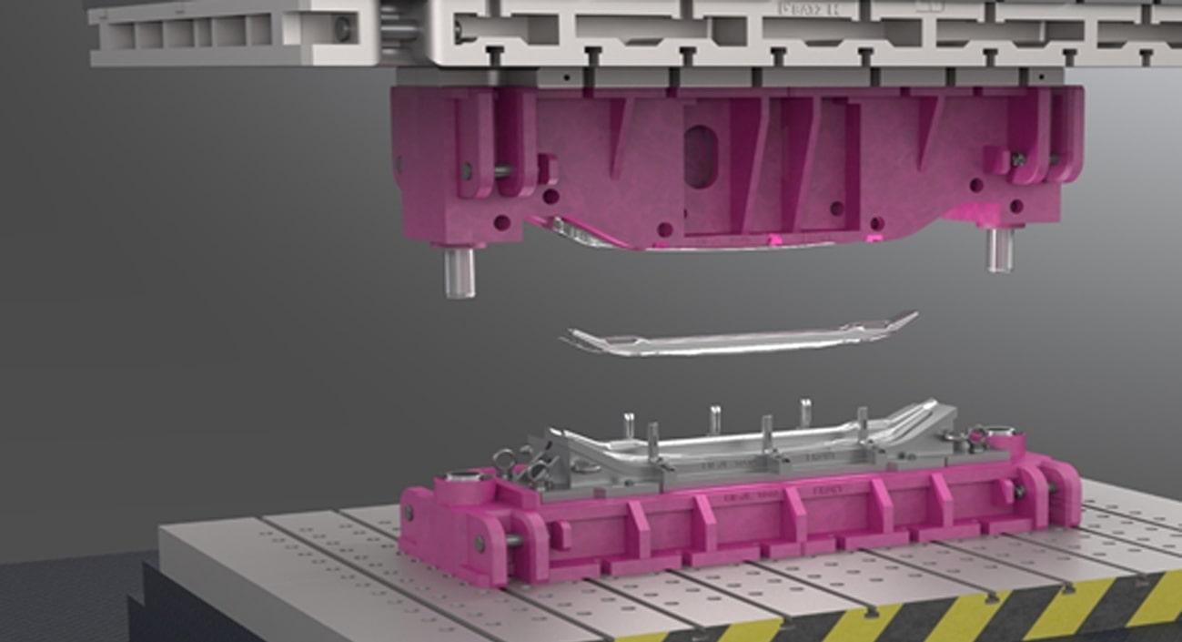
The stamping trials were done by reengineering a die used for hot stamping of boron steels. The die was originally built to hot form 2.3 mm thickness press hardening steel (USIBOR 1500) into a rear bumper, which is a critical car component for passive safety. The aim of the tool reconditioning was to machine the die surface to a nominal gap of 3 mm, being the thickness of the AA7075 and AA6083 aluminum sheets used to form an aluminum bumper fulfilling the car manufacturer’s mechanical and geometrical requirements as well as enabling a high lightweighting of the component. The reconditioning of the tool consisted in the following steps:
- Clone the old 3D surface of the 2.3 mm thickness bumper into the new 3 mm one (Figure 2).
- Simulate and generate the optimal die surface for hot forming a 3 mm aluminum alloy bumper using AutoForm.
- Perform the try-out thermography study in tool-shop and optimise the surface geometry in order to increase the quenching efficacy.
- Machine the old die surface according to the new optimised surface.
- Readapt all die features to match the new geometry (plates, press bench, transfer feeder claws, sheet supporters…).
- Assemble the die and execute the first forming trials for the die spotting until desired final quality was reached.
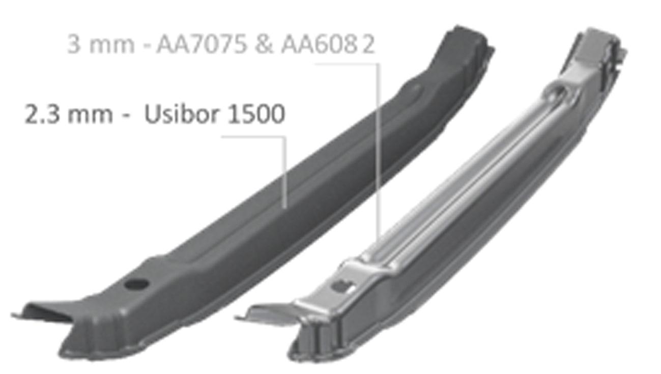
Figure 2: 2.3 mm Boron steel vs 3 mm Aluminum Bumper.
The trials were performed at the hot stamping line inside the industrial facilities of Batz equipped with HOTTEKNIK features (Figure 3). The line consists of a servo-mechanical hot forming press patented by Fagor Arrasate, an automatic feeding system and a multilevel furnace. The line was designed for press hardening of steels. Therefore, feeding system and other peripheral features were adjusted to the needs of aluminum alloys.
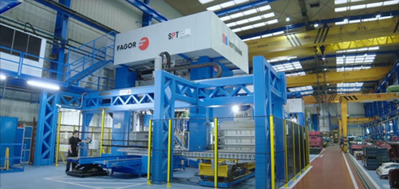
Figure 3: Hot stamping line equipped with the world’s first Servo-mechanical hot forming press.
Fem Simulation & Setup
In order to obtain an accurate FEM simulation model, a deep material and process characterization is required to implement them as input parameters. For that aim, the following test and measurements were performed at Mondragon Unibertsitatea laboratories and Batz facilities:
- The new machined tool surfaces were 3D-Scanned using GOM Atos software to enable the modelling of the reconditioned dies (Figure 4). The scanned surfaces have been directly imported in AutoForm, so that the simulation leads to a more accurate contact distribution.
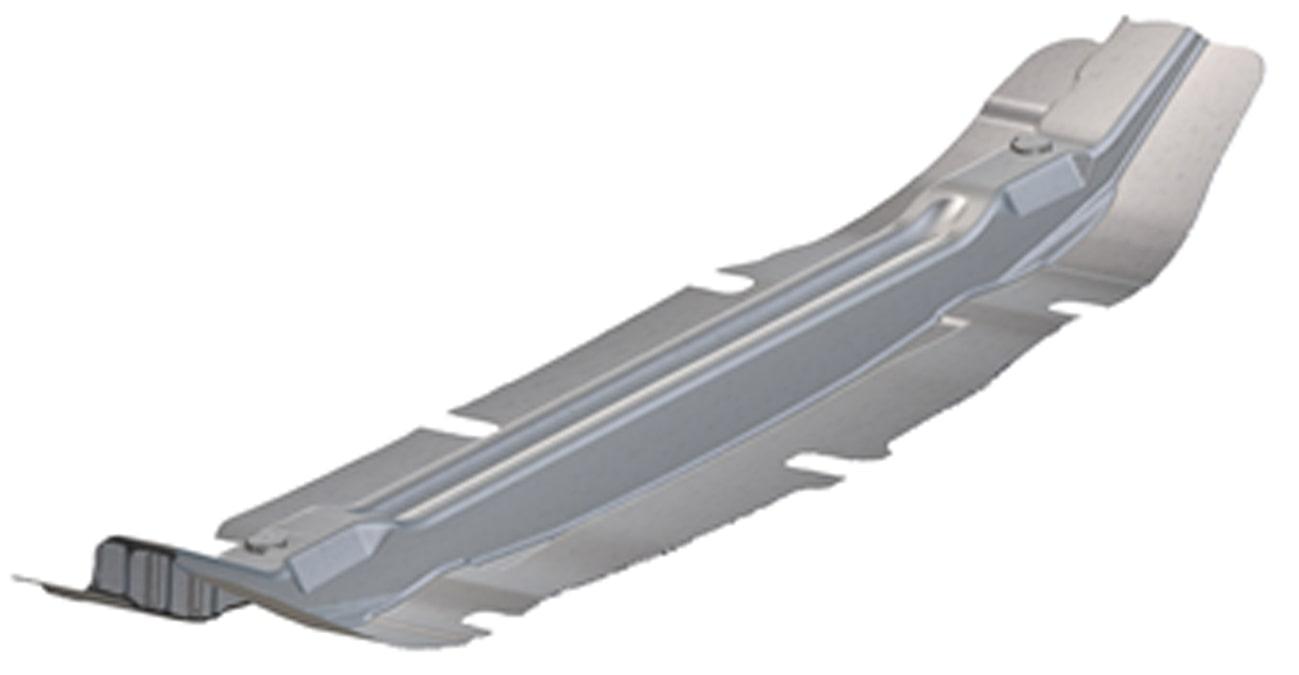
Figure 4: 3D Scanned tool surface with GOM Atos.
- Mechanical characterization: Hardness, tensile tests and energy absorption capacity were tested.
- Thermophysical characterization between 20 – 550 ºC: Density (Dilatometry), Heat Capacity (DSC, Differential scanning calorimetry), Diffusivity (Laser flash method) and finally conductivity.
- Thermomechanical characterization between 20 – 550 ºC at different strain rates ranging from quasi-static 0.001 s-1 to 10 s-1.
- Heat Transfer coefficients (HTC) between aluminum-air and aluminum-dies from 0 MPa to 35 MPa pressures.
- Friction coefficients: Hot ring test were performed in dry and wet conditions to obtain the friction coefficients.
- Surface topography characterization of the aluminum sheets was also performed using optical profilemeter through interferometry method. The roughness of the reconditioned die was also measured by the replication method using resins.
- In addition, press velocity and stroke were measured with a draw-wire displacement sensor installed between upper and lower die surfaces (Figure 5) and real kinematics were used in the simulation model.
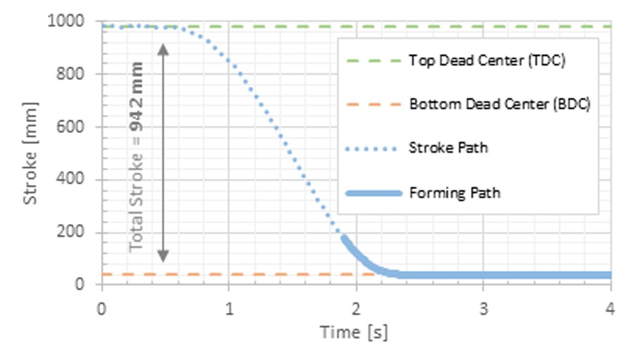
Figure 5: Press kinematics measured with a draw-wire displacement.
Once all input data was imported in the FEM model, AutoForm simulations were used to predict formability issues. As it can be seen in Figure 6 (left), the failure areas were identified using the plastic strain and thinning output of AutoForm. During the set-up of the line, initial components were hot formed and cracked in the same critical areas predicted by the simulations (Figure 6, right).

Figure 6: Plastic strain field output predicted by Autoform (left), first bumper formed without any optimisation (right).
Process parameters were changed to address formability issues without losing thermal requirements which ensure good mechanical properties and accurate geometry tolerances both at the same time. The most relevant modified parameters were the furnace temperature and soaking time (SHT temperature and time), feeder transfer time, forming speed, lubricant type, as well as lubricant amount and distribution, press forces and quenching times among others. For that aim, background knowledge developed by a PhD study about hot stamping of aluminum alloys at the Mondragon Unibertsitatea was applied. Once the process parameters were determined so that the test parts are successfully formed without cracks, the hot stamping line was ready for the line optimization tests.
Line Optimisation Trials
The optimisation tests were fully monitored thermally and cinematically. For tracking the complete thermal cycle of the sheets the following strategy was followed: as the line configuration makes impossible to use thermocouples attached to the parts due to the transfer of the feeder, high resolution FLIR (Figure 7, d & e) and OPTRIS (Figure 7, b & c) thermal cameras were used framing at the press bench and furnace table respectively. Surface emissivity was adjusted for different surface temperatures, viewing angles and precut conditions such as lubricated, dry and coated in order to accurately measure temperatures with a non-contact method. The cooling during the in-die quenching step was tracked using contact thermocouples strategically attached around the most critical zones of the lower die (Figure 7, a). That way, almost the full thermal cycle can be registered.
The kinematic behaviour of the press was measured using the draw-wire displacement sensor, and the displacement and press forces were exported from the servo-mechanical press directly.
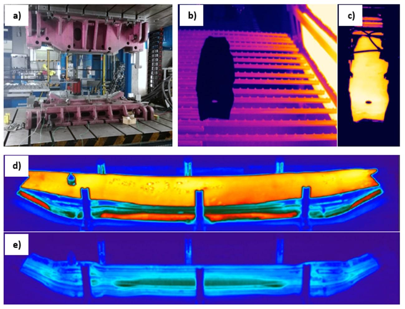
Figure 7: a) Assembled die with the thermocouples attached to its surface, b) and c) OPTRIS thermal camera images of the aluminum sheets before and after the SHT respectively, d) and e) high resolution FLIR thermal camera images of the part before and after forming respectively.
Each forming test was performed as follows:
- The sheet was automatically introduced in the furnace by the feeder at the corresponding SHT temperature for each alloy (AA7075 & 6082) for a certain amount of time.
- In the meantime, the die surfaces were sprayed with different lubricants to reduce friction, avoid galling and increase heat transfer coefficient. The lubricants used for the trials were two non-commercial FUCHS lubricants, which are currently in research phase. These lubricants were specially designed for hot forming aluminum application.
- The heated sheet is quickly transfered by the automatic feeder to the sheet holders implemented in the tool in order to reduce heat loss between the sheet and the dies before forming and quenching.
- The part was immediately hot formed and quenched at different press forces and quenching times.
- Finally, the parts were age hardened to achieve the desired T6 mechanical properties
With the aim of optimising the hot stamping line a wide variety of process parameters were studied, such as the effect of different SHT temperatures and times, different transfer times, press forces, quenching times, lubrication conditions and age hardening types (T6 and T4 tempers). Overall, more than 150 parts were hot formed during the trials with both AA7075 and AA6082 aluminum alloys (Figure 8) in order to optimise a broad range of hot forming parameters and configurations.
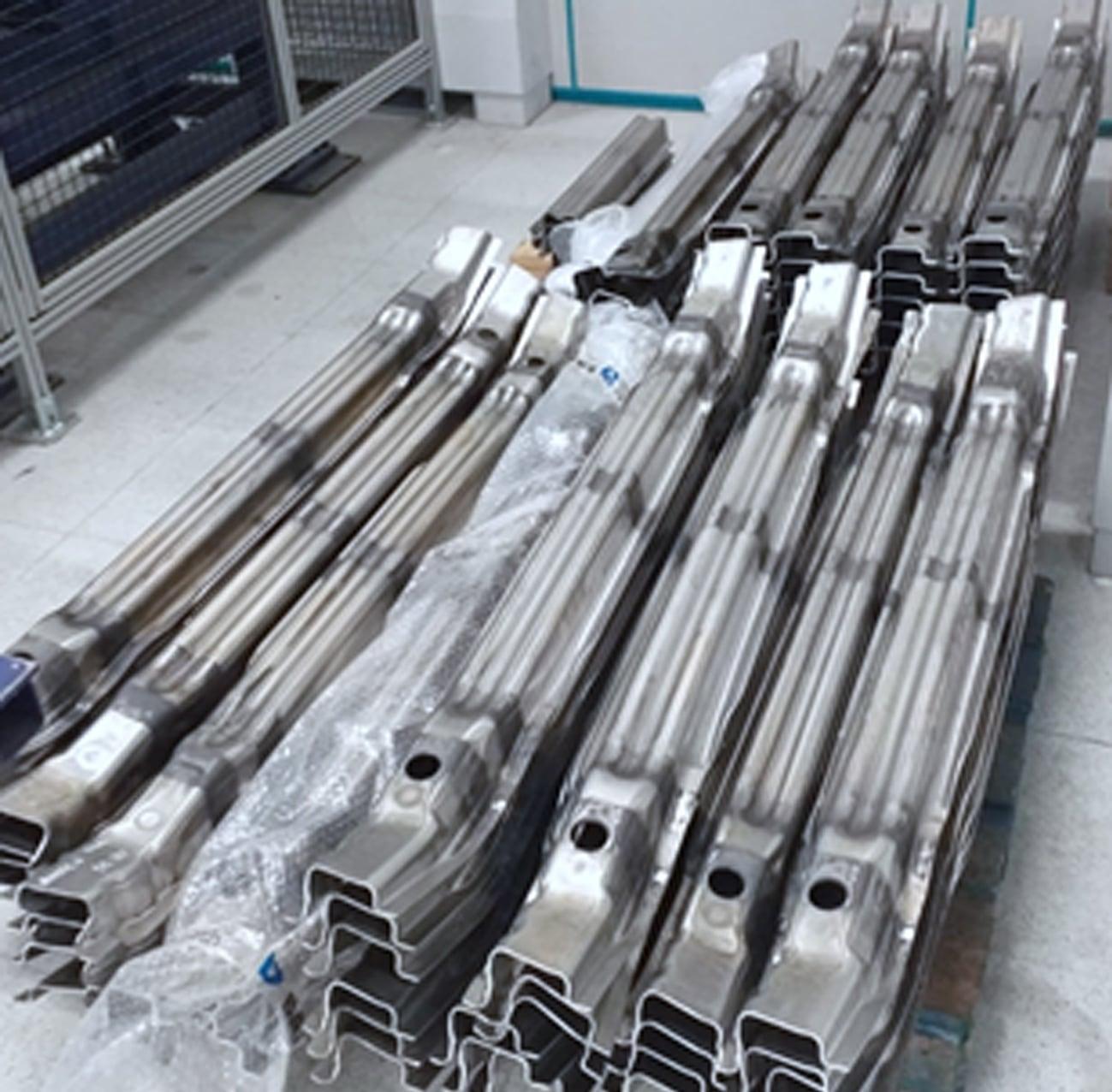
Figure 8: Some of the 150 parts that were hot formed during the tests.
RESULTS: Geometry Tolerances & Mechanical Properties
First, geometrical tolerances were studied. Components with different temper states and formed using different process parameters were measured in Batz using a GOM Atos automatic cell using a control supporting tool designed for that purpose. The deviation of the reference points along the surface of the components were measured and compared with nominal CAD and among different conditions. For example, T6 and WT state (just after quenching) tolerances of the AA7075 alloy can be seen in Figure 9. It is clearly shown that the artificial aging treatment necessary to achieve a T6 state does not significantly affect the geometrical tolerances.
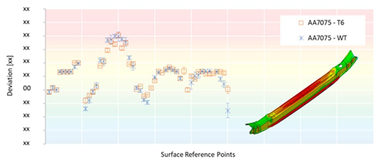
Figure 8: Geometrical tolerances of AA7075 in T6 and WT states.
Secondly, the mechanical properties were analysed. For that, specific cross sections of the bumper were cut to evaluate the hardness through thickness. Indentations were made along 3 sections of the bumper (A, B and C sections) as shown below (Figure 9, up). As it can be observed, even though the hardness measurements of section B are just below the sections A and C, appropriate mechanical properties were achieved for both AA7075-T6 and AA6082-T6 alloys.
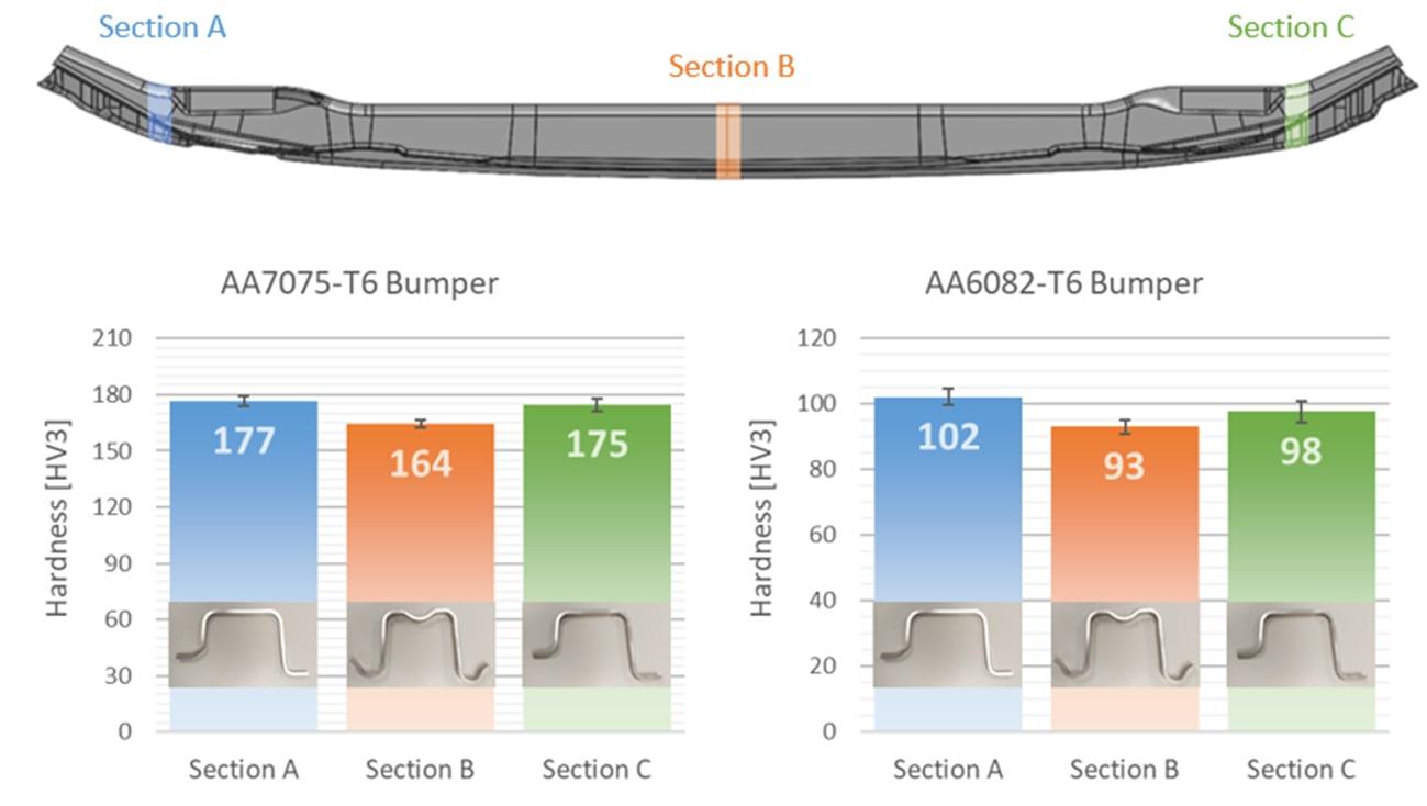
Figure 9: Bumper sections visualized (Up), and AA7075-T6 (left) and AA6082-T6 (right) mean hardness measurements.
The same sections were used to evaluate the thinning of the components. The thinning was evaluated by using a high precision micrometre specifically design for measuring curvy sheet thicknesses. In the graphs below, the change in thickness can be seen for both alloys, and none of them overtakes the maximum acceptable thinning percentage set by automakers.
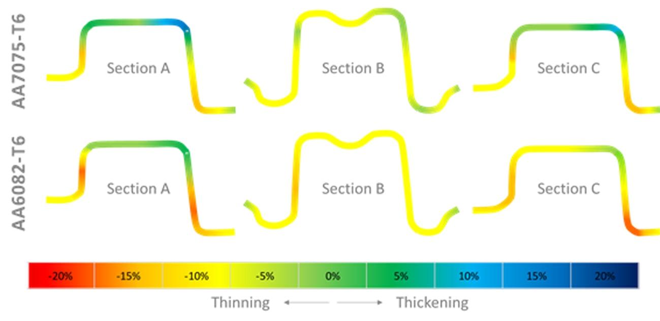
Figure 10: Thinning in the selected cross sections.
Further studies are being made out of the formed components. Additional tensile tests, stress corrosion tests, springback analysis and impact tests to compare the energy absorption capacity among others are ongoing.
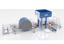
These tests have enabled to write technological guidelines for Fagor Arrasate and Batz companies and have allowed the generation of a deep industrial knowledge about hot stamping of high strength aluminum alloys in the partnership. Nowadays, being a trusted technological partner for hot stamping of boron steels, Fagor Arrasate is also able to offer taylor made hot stamping lines for aluminum alloys equipped with roller or multilevel forced convection furnaces, for low, medium to ultra-high production rates with a production capacity of 600 strokes/hour (example shown at figure 11).
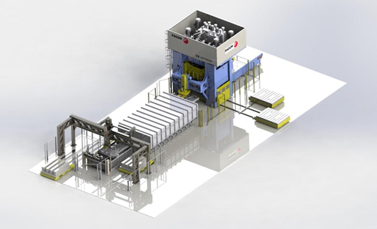
Figure 11: Lay-out of a high production hot stamping line for aluminum alloys.
ABOUT FAGOR ARRASATE _______________________________________
FAGOR ARRASATE is a company specialized in custom design, manufacturing and servicing forming machine tools, forming presses and complete stamping systems for worldwide customers, OEMS and TIER1s. These automated machines include sophisticated production technologies and high-level quality standards for steel, aluminum and composite components.
FAGOR ARRASATE, was created in 1957 and, since then, has expanded its products portfolio and business in a significant manner, being now one of the world leaders in the field. It is one of the 5 biggest manufacturers in terms of turnover and the first one considering the products portfolio.
By Unai Ibarretxe (Mondragon Unibertsitatea), Aitor Ormaetxea (Koniker S.Coop.) and Mónica Carranza (Batz S. Coop.)


