
Compared to traditional spot welding, laser welding offers high surface quality, fast welding speed, excellent sealing, and strong weld strength. These advantages make it particularly suitable for continuous, high-volume processing in automotive manufacturing. It is widely used in the welding of large vehicle components such as chassis, roofs, side walls, doors and body assemblies.
However, the high temperatures generated during laser welding create complex thermal effects. The surface temperature of the welded parts rises and falls sharply due to the high-power laser heat source, leading to significant temperature differences that cause thermoelastic and plastic deformation.
In this study, AutoForm Assembly’s new Line Welding feature is used by the Simultaneous Engineering Team at FAW Volkswagen to investigate the effects of laser welding on a tailgate outer assembly.
Analyzing Laser Welding Deformation with AutoForm Assembly’s Line Welding Module
AutoForm Assembly defines only three key physical parameters:
1. Power: The nominal power of the laser welding equipment.
2. Efficiency: The reduction of nominal laser power to account for equipment conditions.
3. Velocity: The welding speed.
The thermal load results from the heating-cooling cycle are calculated during post-processing. Thermal parameters related to the parts, such as volumetric heat capacity and conductivity, are pre-integrated into the material card.
Pre-Processing Steps
Several steps are required during pre-processing.
First, parameters such as material thickness, physical models, and thermodynamic properties are set. The imported subassembly in this scenario is shown in Figure 1.
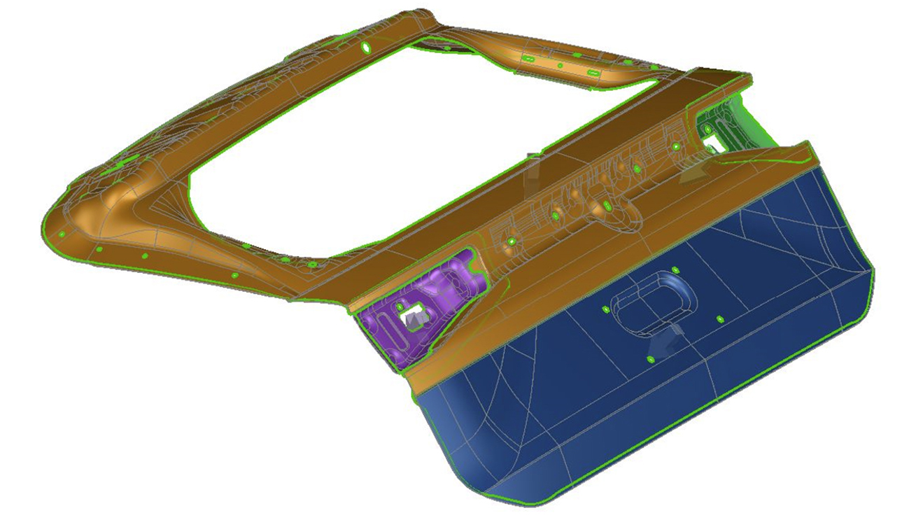
Figure 1: Subassembly imported into AutoForm Assembly
In the process planning stage, the number of operations is established, along with the assembly sequence, resulting in an assembly sequence tree (Figure 2).
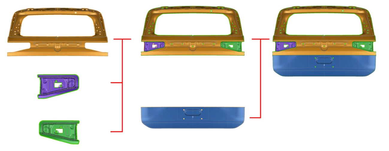
Figure 2: Assembly sequence tree
During loading and fixation, each operation requires defining the loading sequence (Figure 3), loading direction, positioning, and clamping strategy to ensure stability during joining.
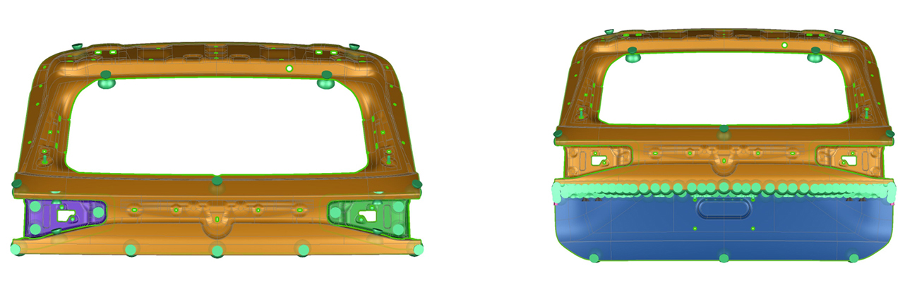
Figure 3: Clamping condition for each operation
Joining involves both spot welding and line welding (Figure 4).
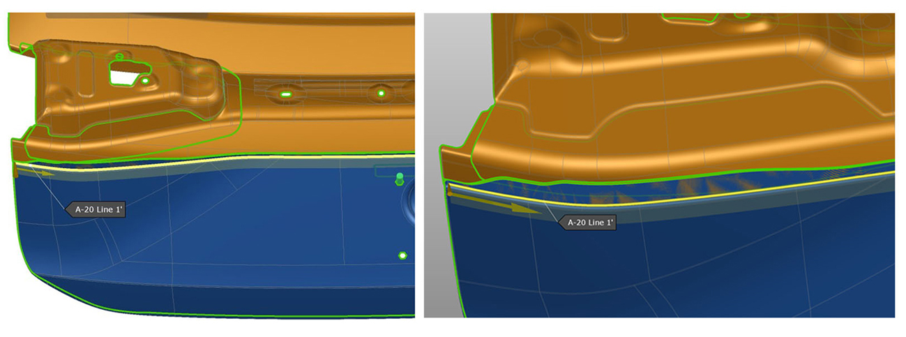
Figure 4: Yellow line represents welding definition (right side zoomed in)
AutoForm Assembly R12 enhances simulation accuracy by incorporating the transient effects of the laser welding thermal model. This includes stepwise development of line joins through the incremental application of thermal loads during line cooling phase, making the analysis results more reflective of real-world conditions.
Interpretation of the Simulation Results
Figure 5 illustrates the dimensional results. Near the laser welding boundary, the outer assembly exhibits a maximum deformation of 1.7 mm in the -X direction. This deviation affects the hemming process and roll-in results.
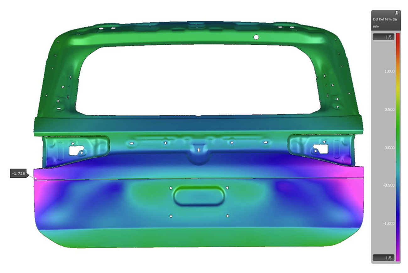
Figure 5: Deformation of the outer panel
Validation of the Simulation Results
After laser welding, blue light scanning of the outer panel assembly confirms significant deformation in the -X direction. The overall trend and actual measurements are highly consistent with the simulation results, as shown in Figures 6.1 and 6.2.
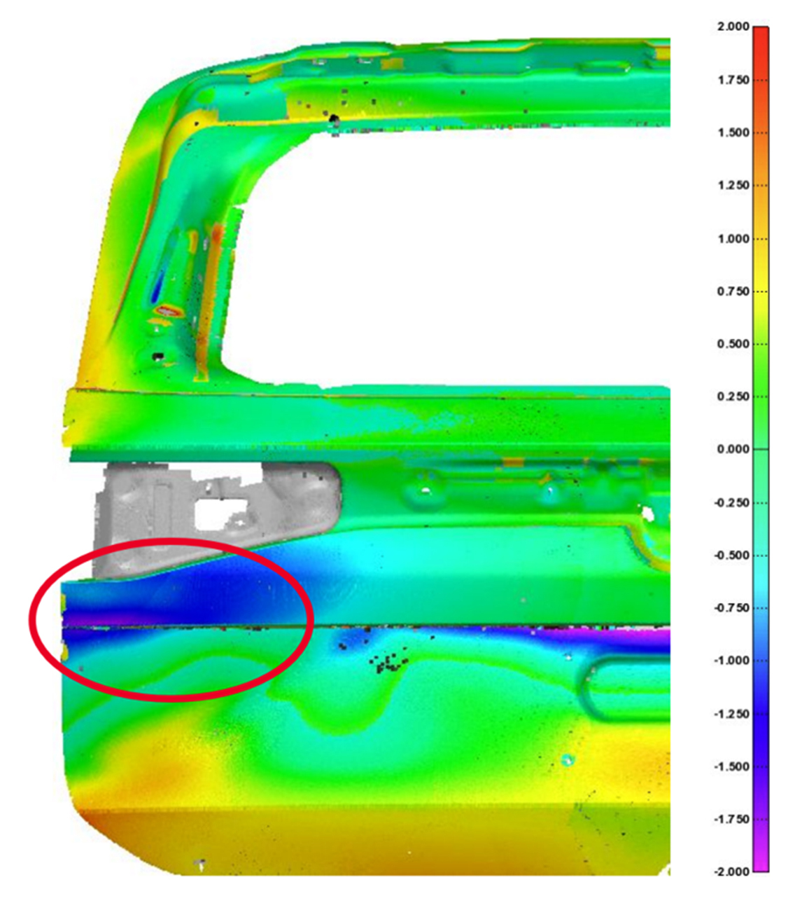
Figure 6.1: Deformation of outer panel by scan
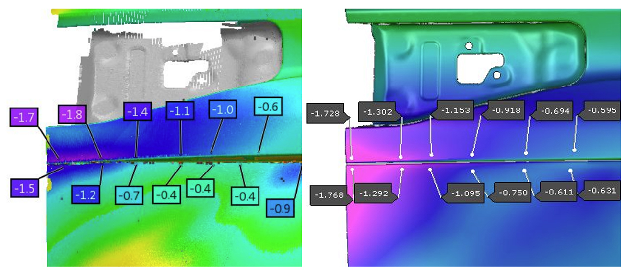
Figure 6.2: Comparison between scan and simulation
During tailgate assembly with the rear bumper, the gap near the deformation is larger than in other areas, creating an obvious defect (Figure 7).
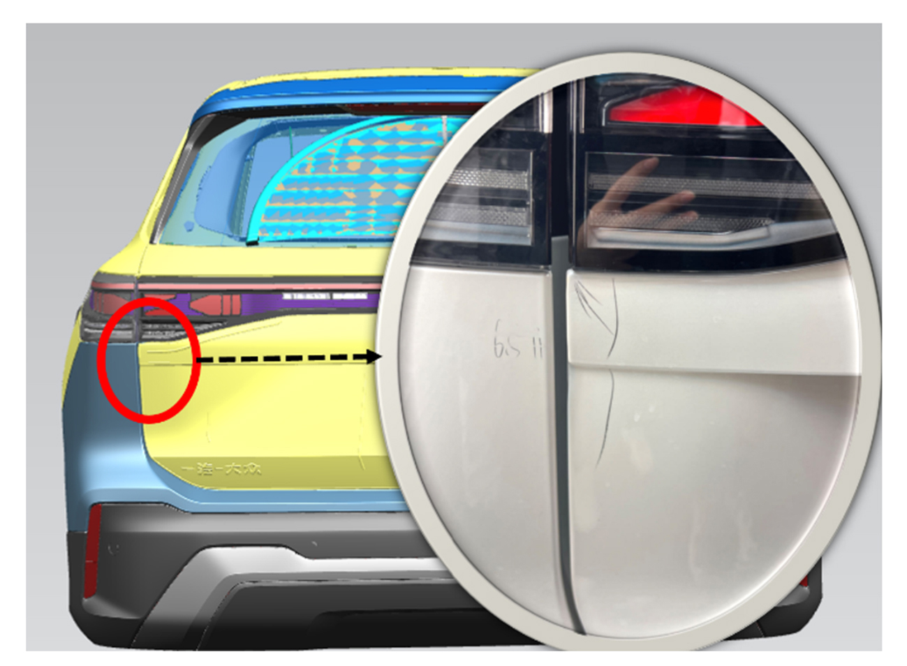
Figure 7: Gap issue between tailgate and rear bumper
Virtual Try-Out and Compensation
By accurately predicting laser welding deformation, AutoForm Assembly allows users to assess adjustability in the assembly process to compensate for deviation. In this case, dimensions were improved through shimming and teaching (adjusted by approximately 2 mm). However, excessive shimming may introduce potential surface defects, as shown in Figure 8.
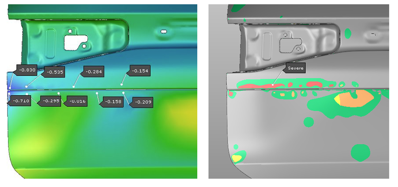
Figure 8: Accuracy improvement and potential surface defects due to shimming
By considering springback effects, users can determine the necessary target geometry to achieve optimal assembly results while avoiding A-class defects (Figure 9).
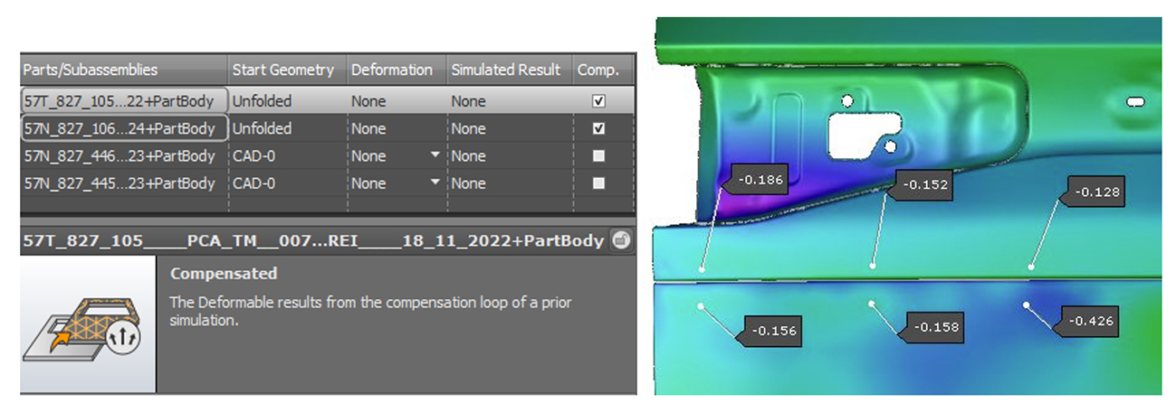
Figure 9: Overcoming deformation through virtual compensation
Conclusion
Deformation after laser welding remains a challenge in the automotive industry. The most effective approach to mitigating deformation is preemptive compensation in part design.
Mr. Zhang, Leader of the Simultaneous Engineering (SE) Team at FAW Volkswagen Changchun, emphasizes the broader relevance of these issues: “We learned from this project that AutoForm Assembly not only accurately simulates the laser welding process and predicts deformation during the SE stage, but also simplifies the compensation process in part design. Additionally, it virtually supports fixture adjustments, significantly reducing risk, cost, and lead time.”
About the author:
Author: Zhang Peiran
Dept. of author: FAW Volkswagen Changchun, T-G-VSC, Product Technology and Ramp Up
Special thanks to Sam Wu, AutoForm China.


?")


