PT Adyawinsa Stamping Industry, established in Karawang, Indonesia in 2005, is a part and tool supplier (including also jig fixtures, racks, etc.) for automakers including Honda, Nissan, and Toyota.
The challenges PT Adyawinsa faced in designing and manufacturing tools for High Strength Steel (HSS) parts were increasing. To become more efficient in handling HSS parts and remain competitive in the market, they embarked on a project with AutoForm to meet the high demands from their production plant.
Mass production of HSS parts was problematic, with parts often falling outside tolerance due to unstable springback behavior, leading to unsustainable costs. The project aimed to stabilize this behavior by maximizing the process window and defining an approach for future projects, all within a three-month timeframe.
The project focused on a specific HSS part, shown in Figure 1.
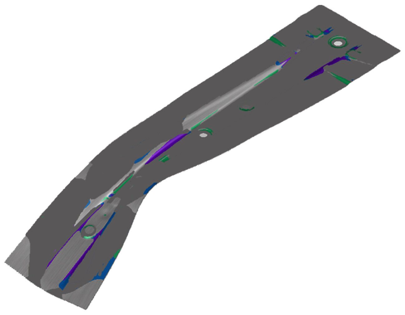
Figure 1: Part studied in the project
The production method for this part included only flanging and trimming operations, without any drawing operations. To expand the process window, the analysis first determined the loading pressure of the nine cushion pins in the press.
We tested different scenarios to find the optimal pressure, using AutoForm’s technology to apply a systematic approach rather than the conventional trial-and-error method. Instead of setting a single force value and adjusting based on the results, we defined a range of pressure values at the start (60 mm from the bottom) and at the bottom of the travel. The pressures curves tested ranged from 8.3±10% tons to 15.18±10% tons. Initial and final values could vary independently, allowing us to consider and test many curves simultaneously.
The graph in Figure 2 summarizes the setup and possible pressure curves within the polygon.
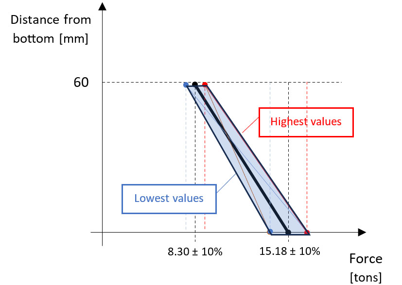
Figure 2: Nominal setup and variable pressure curve
By considering all scenarios, we discovered that only 10% of the part’s total area could be well-stretched without risking splits and wrinkles, as shown in Figure 3.
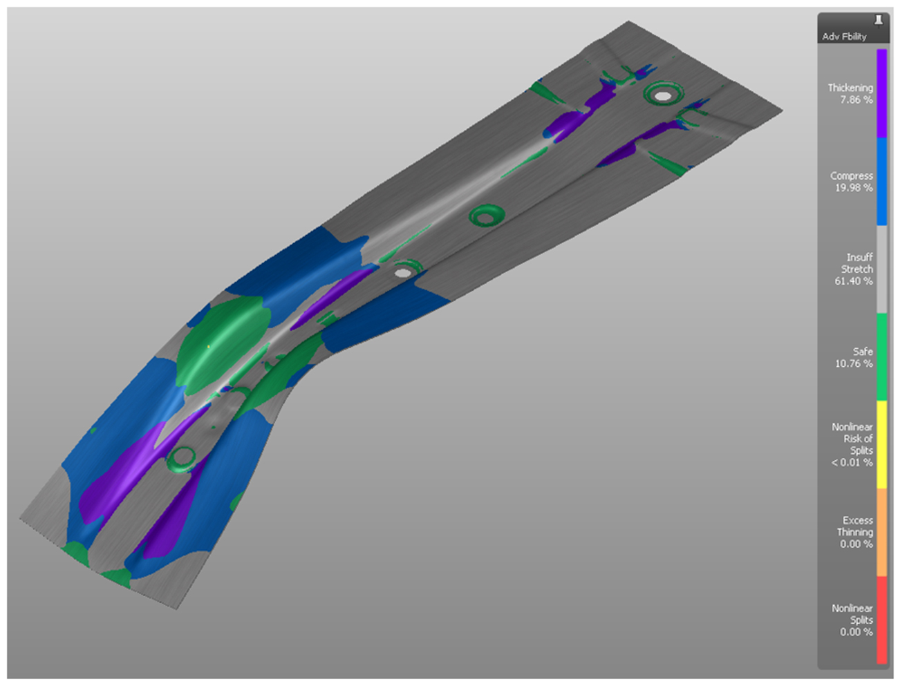
Figure 3: Formability check of project part
After the initial flanging operation, we proceeded to trimming, piercing, and re-strike operations. Finally, we assessed the springback results using a real measurement scenario with two bolts and several clamping points.

Figure 4: Springback measurement setup
At this stage, we evaluated the robustness of the process by considering various parameters that might vary during production, such as material properties and lubrication. As a result, we achieved a stable process, as indicated in Figure 5 (Cp>1 ensures repeatability).
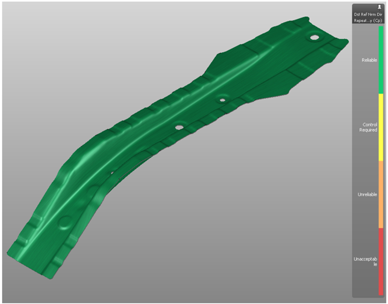
Figure 5: Process stability (Cp)
Although the springback magnitude of the nominal setup was within tolerance and therefore acceptable, the overall process did not meet quality standards (Cpk<1.33), as shown by the large red area in Figure 6.
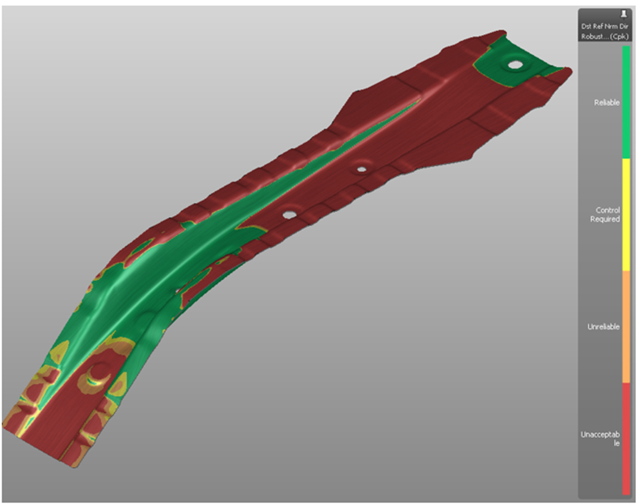
Figure 6: Process capability (Cpk)
In the next stage, the tool geometry tested for robustness was used as a reference for the milling process, followed by tryout. During tryout, the springback values obtained in simulation were compared with real results. The comparison showed a very good match, with the deviation range on the actual part (scanned by Faro Scan) vs. AutoForm simulation being similar (0.7 mm – 3.8 mm). The results of this comparison are shown in the figures below. Both the stamped part and simulation results were both brought into Faro Scan so the same alignment could be applied to both geometries.
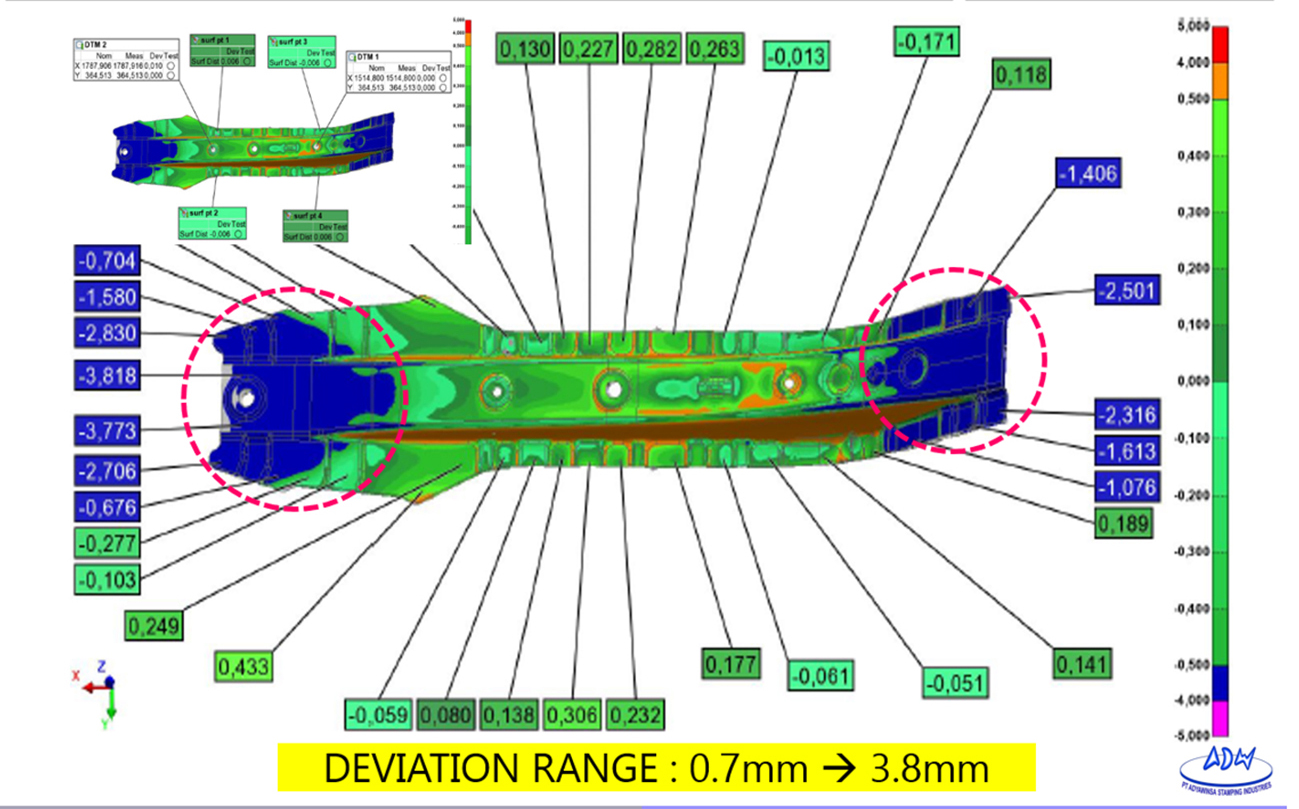
Figure 7: Actual part vs. reference geometry – measurement in Faro Scan
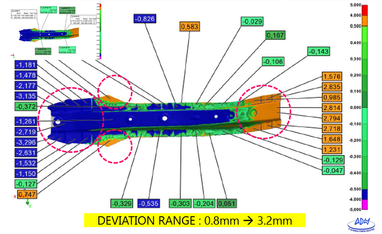
Figure 8: Sheet exported from AutoForm vs. reference geometry – measurement in Faro Scan
Production continues with the tool geometry simulated by AutoForm. Due to the positive results, PT Adyawinsa now develops all high tensile parts independently, implementing the process used in this project.
Special thanks to Ismail Herlambang, Supervisor at PT. ASI, and Ikhsan Dwi Nugroho and Fernanda Aprian, process engineers and AutoForm users at PT. ASI.


