
The manufacturing process of a trunk lid inner panel is very sensitive to fluctuation of temperature and material properties. The result is frequent wrinkling and cracking during production. To solve this problem, the production performance is systematically studied using CAE analysis and optimized with respect to process parameters, die geometry, equipment settings and sheet metal properties.
The trunk lid inner is a standard body inner panel. The surface shape of the part is complex and it has large overall dimensions with many bosses and grooves that tend to crack and wrinkle during the stamping process. In the production of the trunk lid inner panel of this particular vehicle model, wrinkling and cracking often occur alternately, as shown in Fig 1.
Process parameters such as air cushion force and lubrication require adjustment for each batch. This not only affects the production efficiency, but also produces more repair and scrap, making it a particularly urgent problem to solve.
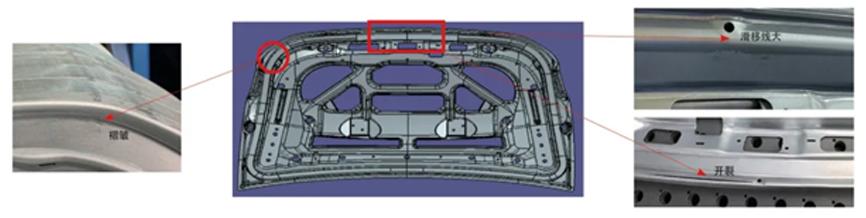
Fig. 1: Part defects (wrinkling, slip line and cracking)
1. Essential information
1.1 Process scheme
This part is stamped using five operations, according to the following scheme:
OP10 Drawing; OP20 Trim / CAM Trim / Pierce; OP30 Trim / CAM Pierce / Pierce; OP40 Restrike; OP50 CAM Pierce / Pierce. The drawing shape of OP10 is shown in Fig 2.
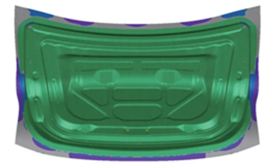
Fig. 2: Drawing shape
1.2 Sheet shape and properties
The sheet metal blank is shaped like an arc, as shown in Fig 3. See Tables 1 and 2 for the sheet’s information and properties, respectively.
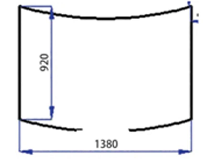
Fig. 3: Sheet shape
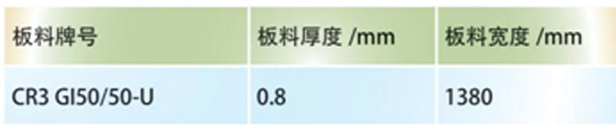
Table 1. Sheet information
Table 2. Sheet properties
2 . Problem analysis
2.1 Low forming margin
From the results of the part’s CAE analysis, thinning is 25.9% (Fig 4) and max failure is 0.9 (Fig 5). Consequently, there is a high risk of cracking, with an insufficient safety margin in the design stage.
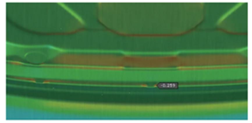
Fig. 4: Thinning
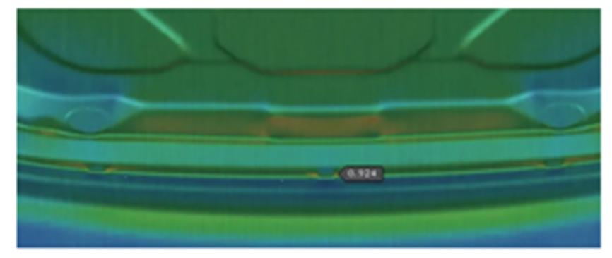
Fig. 5: Max failure
The production verification shows that the die has a window of 12mm of material draw-in from sliding and wrinkling to part cracking, as shown in Fig 6.
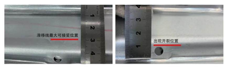
Fig. 6: Die margin range for slip line is about 12mm
2.2 The die is sensitive to temperature
In the early stage of production, due to the low temperature of the die, the slip line is large. The temperature of the die continues to rise due to the friction between the sheet metal and the die in the middle and late stages of production. According to the principle of thermal expansion and cold contraction, the gap between the upper die and the blank holder will become smaller, increasing the resistance of material flow and making the parts prone to cracking. From the beginning of production to about 950 pieces produced, the position of the slip line changes by about 9mm, as shown in Fig 7.
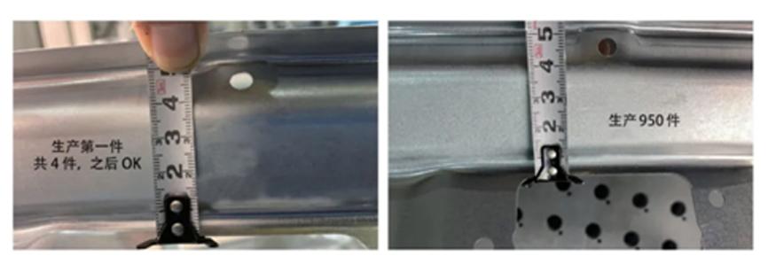
Fig. 7: Change of slip line between start of production and 950 pieces is about 9mm
2.3 The die is sensitive to fluctuations in sheet material properties
The die is sensitive to performance fluctuations in the sheet metal. During the production process, the slip line position also changes by about 6mm after changing material coils, as shown in Fig 8.
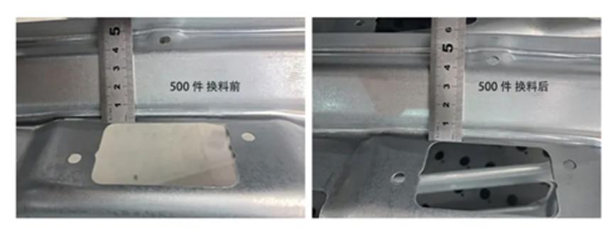
Fig. 8: Change of slip line between different coils is about 6mm
3 . Solution
3.1 Oiling adjustment
By increasing the oil coating, the lubricity of sheet metal can be increased and the cracking of parts can be improved. After production verification, the oil coating on the upper surface is finally changed from 0.5g/㎡ to 1.0g/㎡. The comparison before and after oil coating change is shown in Fig 9 and Fig 10.
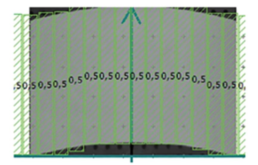
Fig. 9: Before oil coating change
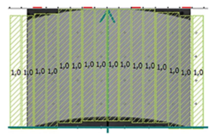
Fig. 10: After oil coating change
3.2 Add blowing device
The compressed air provided by the equipment is used to blow air and cool the die; the added blowing device is shown in Fig 11. Through air blowing and cooling, the mold temperature is kept as stable as possible.
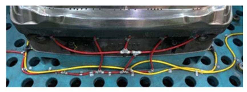
Fig. 11: Added blowing device
3.3 Material performance monitoring
Each batch of coil material must be detected and monitored, as shown in Fig 12. If there is a large fluctuation in sheet material performance, an early warning can be given quickly, and necessary plans can then be formulated in advance of coil change to reduce online shutdown and parts repair and scrap.
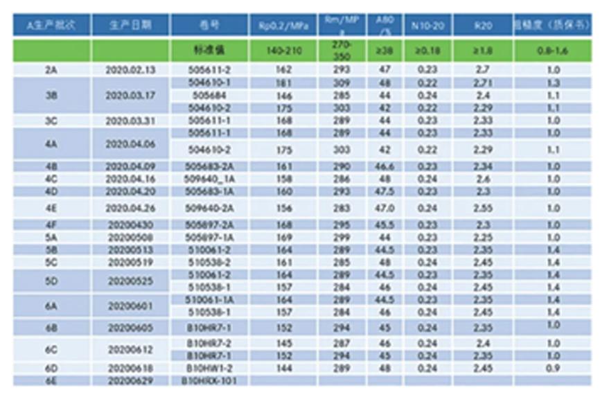
Fig. 12: Material performance monitoring
3.4 Using the segment editing function of drawing cushion force
Through the drawing forming analysis of parts using AutoForm, the generation time of slip line is found to be 45mm before the bottom (Fig 13), and the occurrence time of cracking is about 10mm before the bottom.
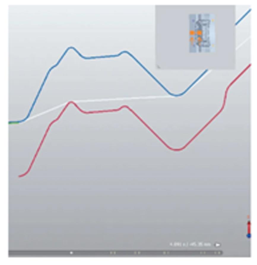
Fig. 13: The generation time of slip line
According to the analysis results, a small blank holder force is used to increase sheet draw-in and store some of the sheet before the slip occurs. When the slip line begins to occur, the blank holder force is increased to control the slip. The sectional setting of the press cushion force is shown in Fig 14, and the pressure curve of the cushion is shown in Fig 15.
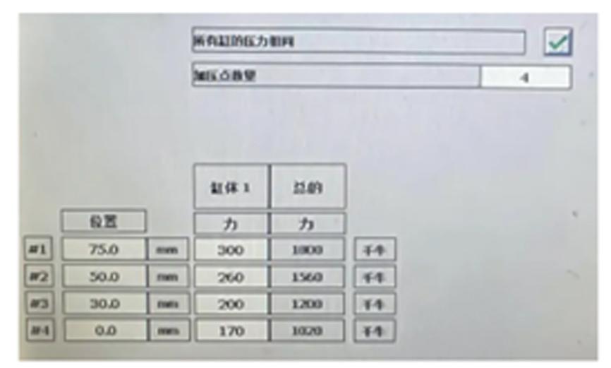
Fig. 14: The sectional setting of the cushion force
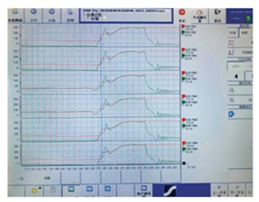
Fig. 15: The pressure curve of the cushion
4 . Project innovation and benefits
4.1 Project innovation
This project aims not only to optimize the dies, but also to systematically analyze and optimize all aspects of the process parameters, dies, equipment and sheet metal.
(1) Process parameters: adjust the oiling parameters.
(2) Die: polish the round corners of the die, reduce the surface roughness, and increase the blowing device to control the temperature change.
(3) Equipment: first time development and use the sectional setting function of drawing cushion.
(4) Sheet metal: monitor the variation of sheet metal properties and formulate corresponding treatment measures.
4.2 Economic performance
(1) Downtime for each batch decreases by about 15 minutes, with production of roughly 56 batches per year. Therefore, about 14 hours of downtime are eliminated annually for this part, and the downtime cost can be reduced by about 500,000 CNY (Approximately €72,000 or $80,000)
(2) 30 pieces are typically repaired in each batch, and 1680 pieces can be repaired per whole year. The repair time of each piece is about 5 minutes. As a result, there is a 140-hour reduction in part repair hours, with higher quality parts produced.
5 . Concluding remarks
At present, the production of this part is stable. The implementation of this project gives us a deeper understanding of the forming problems of similar parts.


?")


