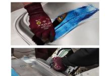
Rapid Tooling for the production of stamped components is still rarely employed, although it proves to be a viable alternative when looking for rapid development and reduction of time-to-market. The feasibility of using advanced polymers in stamping has already been demonstrated, including for forming high-strength materials. With declining production volumes and niche-oriented models, is this an alternative to reduce production costs in a changing automotive industry?
Rapid Prototyping is usually associated with the manufacture of plastic parts, rarely stamped components. In the sheet metal forming however it is previously necessary to consider the concept of Rapid Tooling, in other words, fast tool manufacturing, because it is still necessary a tool for stamping of prototypes. The development of stamping tools is still carried out in several stages that require labor, investment in special machines and different forms of technical expertise in the stages of design, machining, assembly and tryout, as shown below.

Nowadays, a reasonable development lead-time comprehends between 20 and 40 weeks, depending on the size and complexity of the component.
The automotive market shows for some time a strong tendency to diversify the types of models available, plus an increase in the existing variants within a single model. The trend has been further accentuated if we consider the arrival of EVs (Electrical Vehicles). The rapid evolution of the models, the increasing modularization and the variations in geometry have been reducing the production volumes for a given sheet metal component, and this requires greater speed in the development of new ones. As a consequence, the time available for making productive resources available is reduced, while the complexity of products and production techniques increases. In the early stages of product development, the prototypes and the respective tools need to be available as soon as possible.
This work shows that the combined use of simultaneous engineering, additive manufacturing and the use of simulation tools can reduce the time needed to develop new stamped products. The CAD design phases of geometry and simulation were verified using a model produced on a 3D printer. Then a small series of sheet metal prototypes was produced, using a tooling made of advanced polymers. Afterwards, the quality of the piece was checked. During the development of the work, emphasis was placed on a rapid but robust development process. Finally, the time required to complete each stage was counted and compared. The methods used were:
- Forming simulation using One-step simulation method: This method is commonly used to evaluate the productivity of parts during the development of new sheet metal products. The forming process is simulated backwards, in a single step (one-step). In other words, unlike the real forming process, where everything starts with a flat plate that is shaped in several stages until the piece is finished. Commonly, these programs are used only for quick estimates of the part’s formability, since it is not possible to know the real accuracy of the results obtained. Any further interpretation then comes to be in the field of mere speculation. The advantages that justify its use are model preparation times and very short calculation of results.
- Use of statistical methods in conventional simulation to automate the optimization of process parameters: As a way to find the optimal process parameters, it is currently possible to make use of Sensitivity Analysis. To do this, firstly, variation windows are defined for the process parameters, and then a number of simulations are performed. The result comes in the form of process windows, within which the forming process can be successfully carried out. The user thus obtains a deeper understanding of the factors with the greatest influence on the process under study and the optimal parameters of the process can be determined.
- Visual models made by additive manufacturing (3D printing): additive manufacture processes offer today a wide variety of applications in prototyping. These possibilities range from simple samples for checking the design with the customer to entire forming tools.
- Alternative tool materials for prototyping: alternative materials such as composite polymers offer advantages, for example quick machining and ease of making tool changes. Especially with regard to manufacturing time, the potential of alternative materials becomes clear.
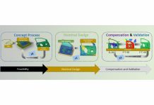
The application of the methods described above modifies the conventional development process chain. Conventional and optimized chains are compared in the figure below. Horizontal arrows mean planning processes, while vertical arrows symbolize manufacturing processes. The overlapping of blocks originates from processes that run parallel or simultaneously. The development stages are distributed over time and divided into three adjacent regions: Objectives Definition, Planning / Virtual Processes / PR and Production.

Case study: Aluminum Frame for a Multifunctional Display
150 pieces of an aluminum frame must be produced to house a touchscreeen on the center console. Objective: to execute the schedule shown above as soon as possible. For this reason, each step of the process is described, following the order of the schedule. Initial situation: the center console (already existing, see following figure) of a car panel needs to be replaced by a piece made of aluminum, which serves as a support frame for a multifunctional display.

All steps, from specifications to cutting the finished part, are briefly described below, starting with the design definition.
Day 1
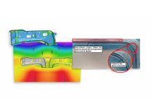
Due to the lack of geometric data of the component, it was first necessary to use reverse engineering to produce the CAD drawing of the component to be manufactured. At this stage, it was possible to evaluate the feasibility of the part using the One-step simulation method. Due to its simplicity, this study could be carried out quickly by the designer. With this, radii considered critical to the forming process could be directly optimized. The results obtained can be seen below.

After this stage, a model for visualization was produced in polymer for a better spatial visualization of the newly conceived geometry. For this, a 3D printing-type rapid prototyping process was used. In the equipment used, thin layers (16μm) of a photo polymer are laid down from a block with eight heads.

The laid down layer is then cured with ultraviolet light. The production of the prototype took 8 hours. As the equipment is automatic, it was possible to carry out production at night.
Day 2
The visualization prototype was evaluated, discussed and minor changes were made. Based on the CAD model now available, it was possible to start the tool design, which generated the information necessary for conventional process simulation. According to the previous analysis, geometry is feasible without problems. However, since it is not possible to obtain reliable detailed results with the One-step program, the geometry had to be simulated again using a conventional simulation method. The program used was AutoForm Incremental. Common problems when comparing the two simulation methods are adjusting the strength of the blankholder force and the exact amount of initial blank material that slides into the matrix (difference between initial and final blank perimeter).
At this point in the development work, additional statistical tools were used to increase the safety of the forming process. The use of these methods is based on the premise that the main parameters responsible for the part quality are known. Therefore, the first step of this type of analysis is to proceed with an identification and classification of these parameters. This requires practical knowledge, expertizing is necessary. On this selection rely the quality of the results of the analysis and the statistical optimization of the process. By varying the right parameters, it is possible to know the effects on the forming process and correct the tools accordingly. Through, using the method it is possible on the one hand to optimize tool parameters and on the other hand to increase the safety (robustness) of the process. However, it is necessary to account for additional time for this type of analysis, which will depend on the complexity of the part and the process. The number of simulation cycles required depends on the quality of the pre-optimization previously performed with the One-step program and on the level of expertise of the simulation specialist. The result obtained with AutoForm Incremental can be seen below.

The satisfactory result of the simulation allowed for the completion of the tool design. It was designed to be built with a high strength composite polymeric material. The main advantages of using this sort of material are:
- Fast fabrication: machining takes place in record time, there is no need for heat treatments or polishing.
- Reduced tryout time: The lower modulus of elasticity of the polymer makes it fit naturally during the forming process, while maintaining the dimensions expected for the product.
It is worth opening a parenthesis to talk a little more about this alternative material:

Despite being contrary to common sense, advanced polymers allow the forming of high-strength sheets with refined details, small radii and surface details. The part showed below was made of steel with 700MPa tensile strength and 1 mm thick. This class of materials allows for fast machining and the making of threads, the use of pins and other conventional elements used in the design of tools. The tool inserts in the image below produced 1200 components until it started to show noticeable wear.

Returning to the original theme of the article, the final toll design can be seen below. Based on it, programs for CNC machining of polymer blocks were made.

Days 3 and 4
After finishing the 3D drawings and machining programs, the tool was finally able to be manufactured. The duration of this step depends on several factors such as the number of machining centers available, the experience of the operators and the type of material to be worked. With the use of polymeric material it was possible to reduce the manufacturing time of the parts by a factor of 3, which shows one of the advantages of this type of material. The steps for manufacturing the tool can be seen below.

Days 4 and 5
After machining of its components, the tool was assembled and adjusted in the press. With the production of the first good piece, the production of the 150 pieces began. After that, the contour of the part was cut and the component mounted on the center console with the touchscreen. These steps are shown below.

The time required for a development like this depends not only on the methods used, but also on the characteristics of each company. The development of a sheet metal product like the one presented in this work can be accomplished in 4-5 days. A description of the times required for each step can be seen in the table below. Due to the use of simultaneous engineering and the consequent parallelization of stages of development, it is not possible to simply add the times obtained.

It is important to highlight the use of polymeric material in this project, which made possible not only a quick manufacturing and adjustment of the tool, but also parts with excellent dimensional and surface quality. It is also important to note that using statistical methods of optimization for more complex, an additional 2-3 days should be counted in the planning.
Final considerations
Why do we use steel in tools? There are several reasons that can be listed, but the main one is the high resistance to wear, which allows huge production volumes. When we do not need large volumes we continue to use steel … simply because we cannot think in an unconventional way. Will the stamping market continue to be large volumes in the future? I believe that the niche of small volumes tends to grow a lot, as it has been happening for some years.
Tribologically speaking, when forming sheet metal using polymers, the wear mechanism is abrasive since there is contact between the surfaces (without lubrication, for example). However, it is possible to achieve an elasto-dynamic regime with extremely low wear. With steel tools, the regime is mixed, that is, there is always metal-metal contact between blank and tool. The main wear mechanism is adhesion, followed by abrasion and tribo-chemical wear, all of which are very difficult to control without the use of ceramic coatings and pre-treatments.
Apart from “wear resistance”, what would be the ideal mechanical properties of a forming die? Steel, with its extremely high modulus of elasticity, requires enormous finesse in the manufacture of the active components of the tool. So much so that the adjustment and tryout steps often consume more than half of the tool development time. Special polymers, in turn, allow the tool to adjust to the process, while controlling the material flow. Controlling deformation is easier than trying to avoid it.
The advances in materials engineering do not stop. Advanced polymers, manufactured through the addition of reinforcers in their microstructure, allow to obtain very interesting mechanical properties, including for the field of stamping processes.
Additive polymer manufacturing processes can offer opportunities not only in the manufacture of components (parts), but also in the manufacture of cheaper and faster manufacturing resources.
Dr.-Ing. João Henrique Corrêa de Souza
 20 years of experience in the stamping industry, working with automotive and non-automotive sheet metal components suppliers, focused on materials selection and optimization, simulation analysis, rapid tooling, tooling buyoff, field formability analyses, manufacturing process improvement, process tribology, and cost savings/cost avoidance projects.
LinkedIn profile here:


