
Rapiit is a company located in Akaiwa City, Okayama, specializing in prototype stampings, tool design, and tool making for automotive parts manufacturers. Rapiit increasingly handles the entire process in-house, from drawing 3D data from the desired product shape and making tools to processing into products.
However, Rapiit was facing a number of issues:
- Quotations were made based on precedents. When estimation was difficult, the quotations tended to be redundant to avoid risks.
- For tool-making processes, CAD was used to model a tool, but process engineering was based on experience and intuition. Additional processes were inserted when the risk was deemed high.
- Defects were often found only after the tool was created and used for stamping, requiring repeated corrections. Additional processes were inserted about once a month.
- On the shop floor, it was impossible to foresee how many tool reworks or additional processes would be necessary, making production scheduling difficult and often resulting in wasted time and labor.
The work process (Fig. 1) clearly shows that issues were found throughout, from upstream to downstream.
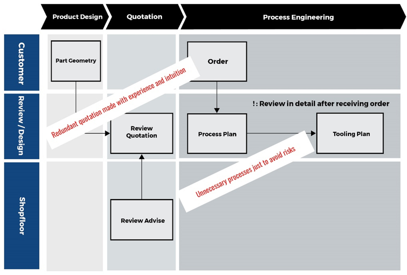
Fig. 1: The redundant process.
Rapiit worked on changing this work process with the help of AutoForm. Initially, they did not reach their goal because engineers were too busy with their own tasks. So, managing director Shigemoto assigned CAE engineers Ichihara and Noyama to be in charge of simulation. They learned the simulation technology and skills, then effectively incorporated the simulation into the work processes.
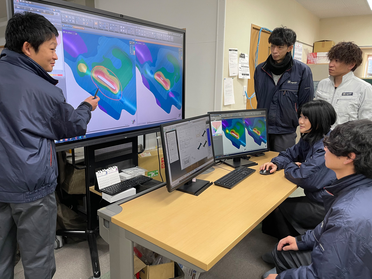
Fig. 2: (From the left) managing director Shigemoto and CAE engineers Ichihara and Noyama (Behind) tooling engineer and sales representative
The new process is as follows:
- When creating a quotation, particularly for a complex part, AutoForm is used to estimate process layout, blank and tool sizes.
- In the quotation stage, AutoForm-DieDesigner is used for process engineering and tool modeling.
- In the process engineering and die design stages, defects are addressed before moving on to the tool making and tryout stages.
- Trimlines are also reviewed in the tool design stage.
- The simulation is used to predict regions with a risk of defects, and this data is passed on to the shop floor for quality assurance during tryouts.
The new work process (Fig. 3) shows that CAE simulation is used from the early stages to identify and resolve defects before the tool is made on the shop floor.
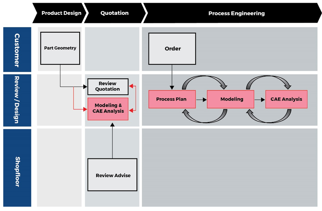
Fig. 3: New work process flow
Unlike making a tool for mass production, ultra-high efficiency is indispensable when making a prototype tool due to the extremely short production schedule. A minor rework or slight modification at the shop floor can result in delivery delays and cost increases. Incorporating AutoForm into the work process brought these benefits:
- More precise quotations can be made with AutoForm, making cost increases during tryout less likely and eliminating the need for additional processes simply to avoid risks.
- AutoForm can be used to optimize tool size, particularly by optimizing a layout for double-attached parts.
- Rework time during tryout is reduced by 50-60%.
- Blank material consumed during the tryout is reduced from 5 to 2 sheets, because the blank size is optimized prior to tryout.
- Stamping at the initial tryout becomes more precise. Previously, only 60% of the simple parts and 30% of the complex parts satisfied the requirement. Now, the rates have improved to 80-90% and 60-70%, respectively.
- At the shop floor, there is no need to estimate trimlines for tool modification.
- As a side benefit, tool designers can learn more about stamping through simulation, or so-called “virtual tryout.” With deeper knowledge of stamping, communication between designers and the shop floor becomes smoother.
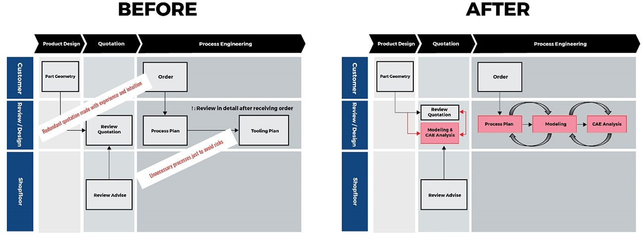
Fig. 4: Comparing the before and after processes
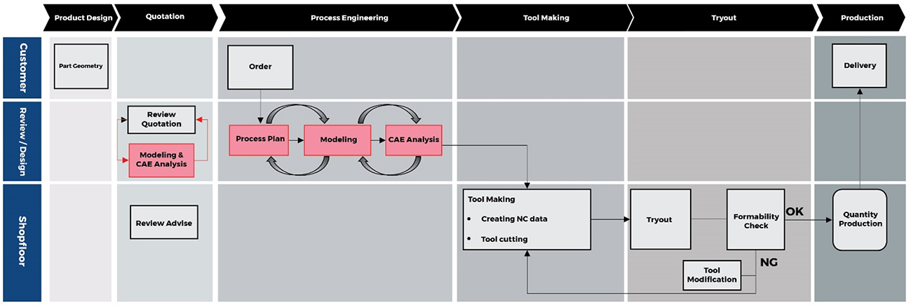
Fig. 5: The entire process
The figure below shows how the size and position of the blank are optimized, and the sliding conditions are modified to reduce two processes into one while improving the thinning rate.
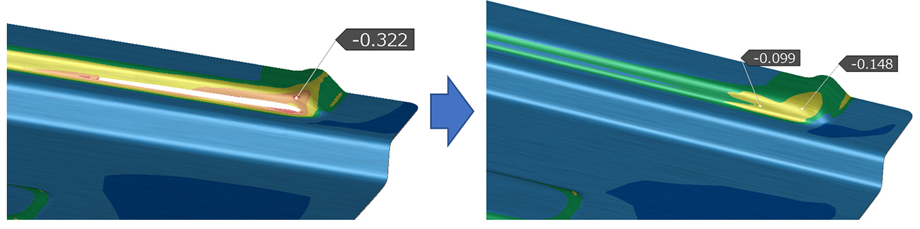
Fig. 6: Two processes are reduced into one and thinning is improved
As for springback compensation, during the tryout, stamping with a compensated tool produced panels with sufficient accuracy, as shown below.
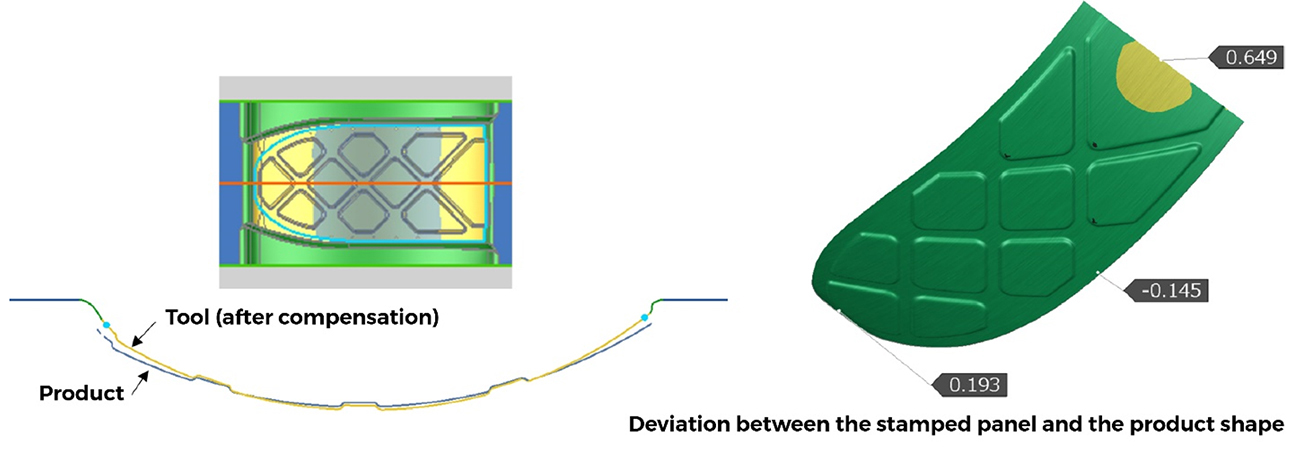
Fig. 7: Tool after compensation
RAPIIT Corporation
Establishment: March 1955
Location: 50-19 Kosegi, Akaiwa City, Okayama
Number of employees: 30 (as of February 2023)
Business: Prototype stamping, tool design and tool making
Manufacture and forming of thermoplastic resin composite material: CFRTP. 3D laser processing, design and manufacture of jigs and inspection tools. Data creation using 3D CAD, reverse engineering. High-mix low-volume production.
URL: http://www.rapiit.com/


?")


