Simulating the manufacturing process for stamped products is increasingly critical in today´s world. To achieve results that will match reality, it is important to work with high quality surfaces. In addition to surface quality in the CAD sense, the surfaces must also closely represent the physical tool. The shape being used for simulation should match the shape as machined. To that end, this article will address some direct customer feedback to support their work efforts in creating, simulating, and ultimately matching the machined tool surfaces as early in the design phase as possible.
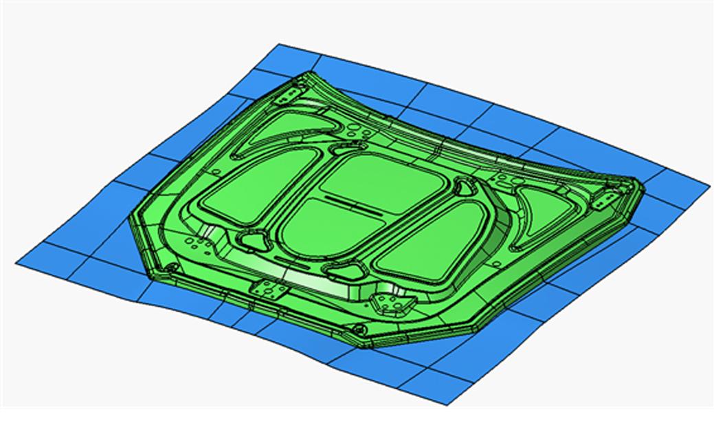
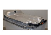
Figure 1 – Draw Surface Tool – Punch and Binder
Constant Changes
In a standardized process, it is easiest to make changes in the concept of the tooling surface. In other CAD software, this change takes a long time, is tedious, and may be confusing regarding how to complete the modification. This then leads to redesign of the changed areas.
According to a report by software user Allan A. de Moura, Engineering, Projects and Simulation Director of the Vtron design office: “Modifications to the drawing model and cut distributions occur frequently during the simulation verification and validation phase Method Plan with the client. The module mentioned helped us precisely in this regard. Changes to shapes and cut lines within the software structure are incredibly interactive and connected, so creative time is not wasted on reconstructions of lost features.”
This standardization allows the user to create the cutting tools in a simpler and clearer way compared to standard commands. When designing the trim and scrap layout, dedicated analysis tools are available to quickly confirm trim angle conditions.
Compensation Surface Quality
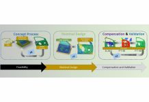
When compensation is performed in simulation software, the deformation applied to the geometry can cause superficial defects in the tool, which can then be passed on to the final part. This is fine in simulation, providing the most efficient way to arrive at a stable compensation scheme. However, the surface quality must be managed if it is to be machined on production tooling. Taking advantage of the communication between simulation and ProcessDesignerforCATIA, this simulation work can easily be applied to the CAD surfaces with minimal effort.
According to Allan, “The surface compensation feature by importing a vector field facilitates and advances the process of finishing surfaces for machining, creating a cohesive and flawless geometry. The software is a fantastic resource that facilitates the process of creating the designer.”
User Leonardo Fernandes Dompieri carried out the compensation work as in the example below.
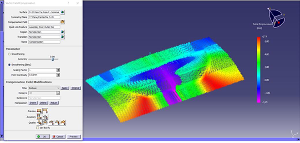
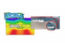
Figure 2 – Vector Field
First, a twist was applied in the simulation software to correct the drawing operation of an upper region (Class A). After the correction loops, the vector field generated by the simulation software was exported to be used in the mentioned module.
The user applied the compensation directly to the nominal tooling surface to achieve the desired shape as simulated. After the analysis of the resulting surface, using the available analysis tools, the quality of the modified geometry was approved and sent to begin manufacturing. According to Leonardo: .”
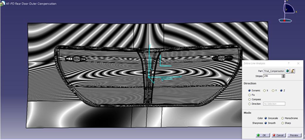
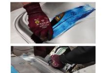
Figure 3 – Class A surface evaluation
Companies today are interested in two drivers to achieve success: time and quality. AutoForm-ProcessDesignerforCATIA delivers this to users, providing an essential tool in the development of stamping tooling projects and delivering a healthy return on investment with faster results and excellent quality.

Adilson Calmona Dutra – Mechanical Engineering graduate from the Instituto Mauá de Tecnologia (IMT) and member of the AutoForm technical team, working in technical support and with projects to implement the technology. adilson.calmona@autoform.com.br
Colaboração:
 Allan A. de Moura – Engineering Director of Project and simulation at the Vtron Project Office.
 Leonardo Fernandes Dompieri – Surface and Simulation Technician at Gestamp Paraná.


