
Understanding the Birth of Springback and Form Better Parts
In this blog post AutoForm Technical Account Manager Mark Hineline from USA reveals how to get the most out of your simulations by breaking down all the factors that influence your results when dealing specifically with springback. Follow this advice and you’ll sidestep several issues that would otherwise show up in tryout.
Introduction
Utilizing today’s simulation technology provides very accurate results for controlling springback. However it is critical that the simulation process and parameters match those of the real tool producing the part. It is still all too common for companies to apply the “Close enough” attitude in simulation even when this leads to unmanageable outcomes in the press room. If you are willing to accept the “close enough” attitude from your simulations then you should expect “close enough” results from the real tool. However it is often that “close enough” leads to extra re-cutting of tools that would not be necessary if due diligence is given to simulation, which is then matched in the real tool. Due diligence means that you need to consider things like:
- Blank outline
- Proper material specifications
- How is the trimming done
- Draw conditions such as full draw or “short sheeting” the draw
- Draw in amount
- Need to stretch the panel to resist springback
- Scaling of tools being applied
- Proper locating of the panel from operation to operation
- Proper forming of flanges
These may not be all of the influencing factors to consider, as this may change depending on the part and the forming process. The more exhaustively and diligently these physical influences are accounted for in simulation, the closer the physical panel will eventually match the simulation outcomes. After all, the intent of simulation is to mimic the real process and avoid as many pitfalls as possible. Of course it would be nice to eliminate every issue within simulation, but as we all know this is not likely to be the case when it comes to springback. However being thoughtful when processing your simulation pays off greatly when it comes to the cost of building tools. After all, isn’t that why you have simulation?
Let’s examine the key influencing factors in this post.
Understanding Your Blanks
The material properties of the blank and the necessary outline is likely the most important influence to be considered. Ultimately if you do not start with the proper material description and correct blank size, everything that follows is making some type of assumptions. For example, if you assume the material you are using in simulation is “close enough,” or even worse assume you are defining a “worst case” material, then you should also be assuming your simulation results are not going to match reality! Often we see an attempt to create the “worst case” material by altering a “close enough” material file. Unfortunately this material often can never actually be obtained from a steel supplier as it is an unrealistic material. By doing this you are often over engineering a tool or simulating a completely unreliable or unrealistic process to build tools too. The birth of springback is at the material properties!
It is necessary to evaluate the part with early feasibility results as there is more to this than simply unfolding the part. It is not as simple as just flattening the 3D part geometry. The unfolded part drives the desired draw-in amount, which drives formability, which drives the proper blank size, which drives the nesting of the blank into the coil, which then drives cost. It is imperative to the process to know the geometry which allows the part to be stamped as designed. All of this can be discovered with early feasibility software solutions. So not only do you obtain the desired blank outline, you also will have formability results very early into the process. This is all information that you expect to get from simulation but this is also the beginning of how springback is being introduced instto your part.
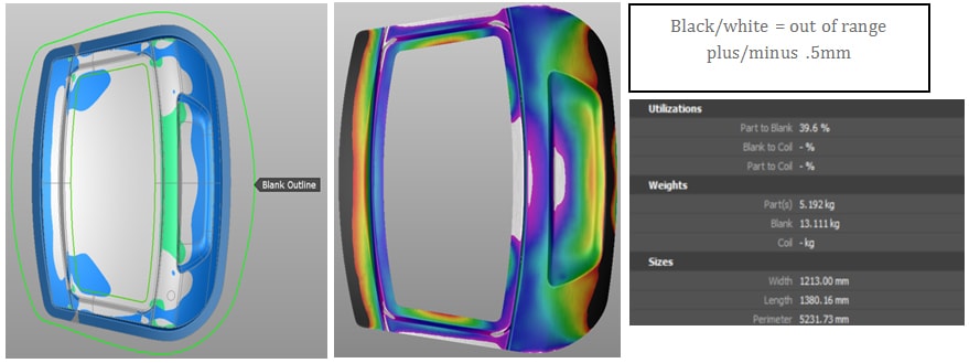
Fig. 1: Example of going out of range of springback tolerance.
In this example you see the difference that stretching (straining) of the sheet metal makes towards utilization, formability, and springback.
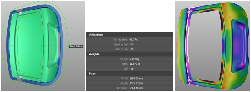
Fig. 2: Adequate straining of sheet material.
But wait! I thought this is a story about controlling springback? Of course it is. Springback is not simply something you realize or even think about until after simulation has been done or the part is formed in the press. Springback is affected by the decisions you make from the very start of your design process. As early as you start to think about a process you also need to consider how this process affects the entire scope of formed part in which springback can be a very big issue.
At this point you have already considered:
- Material properties
- Drawing conditions
- Formability related to stretch the material to produce adequate plastic strain
- Produced the blank outline
- Material utilization
All of which affect springback
Great, now I can continue on and not worry about springback! Well not so fast. You have just defined the proposed process to form the part. Springback results are not yet available. The images were used to simply drive home the point that what you do at this stage of planning will have an effect on springback and you may need to adapt your design during the simulation process. All you have at this point in time is the desired blank outline, the cost of it, and a plausible forming concept. You still need to build the tools to match your thoughts and provide the desired outcome. Moving forward we will assume you have the proper tooling defined using your chosen software solution prior to CAD or you have imported the tool geometry from your CAD software.
Key Factors – Forming Process and Tooling
Now that we believe we have the proper tooling geometry that efficiently stretches the material, trimming is defined and optimized, as well all secondary forming is accomplished we should now have the perfect process, correct? However, we often see in simulation that other important process parameters are ignored such as:
- Scaling the draw geometry
- Proper application of draw beads
- Fitting the drawn panel correctly onto the trimming operations and following secondary operations
- Trimming the panel with tooling geometry and not simply cutting with a line like a laser (unless this is actually being done)
- Trimming segments are defined correctly in each trimming operation
- Tool forces are correct and can be supplied in the real tool
These are all real factors that affect the forming of sheet metal in the physical tooling which have an effect on springback. It is common knowledge that body panels of thin-gauge material being stretched over nominal draw geometry will shrink to less than the nominal part geometry after drawing. To offset this, scaling (making tools slightly larger than nominal) is applied to the draw geometry in the physical tool. Scaling is often ignored in simulation because “We do this during CNC machining and it is not necessary to scale our designed tools”. True, but it is important to apply the scaling in simulation as it reflects reality and it influences springback! If scaling is not applied to the draw die geometry the drawn panel will likely not fit properly onto the next operations due to shrinkage.
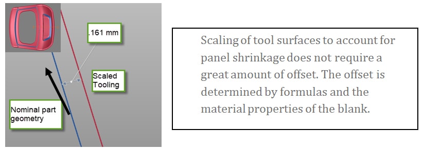
Fig. 3: Offset controlled by scaling tools.
It is also important to allow the panel to relax with free springback after forming and then to allow a locating of the panel onto the tooling in all of the following operations. If the panel cannot fit onto the next operations, such as the trim dies, it will be resized by the closing of pads onto the posts and then the springback will be different than if the panel had been positioned correctly. It is critical that – all secondary operations tool geometry match what you expect to see in the physical tool. For example if there is a clearing of radii in the physical tools this should also be done in simulation. The clearing radii of secondary operations to match the real tool is not only relevant to positioning of the panel but it is also very relevant to predict proper force estimation for pads. These tool forces become very relevant to the springback of the panel as well. If the pads are opening too much you lose control of springback just as too much force that cannot be applied in the real tool could skew the springback results.
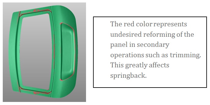
Fig. 4: Undesirable reforming of the panel at trimming.
This also leads us to another commonly overlooked process effect in simulation. All too often the panel is not placed onto tools in the cutting operations. Instead the cutting is simply applied to an un-sprung panel from the draw die with a continuous curve as if the part is being trimmed by a laser. By doing this in simulation it will lead not only to incorrect trim line optimization but also incorrect springback results. The proper cutting steels also should be considered in the simulation. In reality segmented cutting is applied in the real tool, not one giant trim steel cutting the entire perimeter of the part. Each operation cutting sequence affects the sprung panel and how it will locate into the following operations.
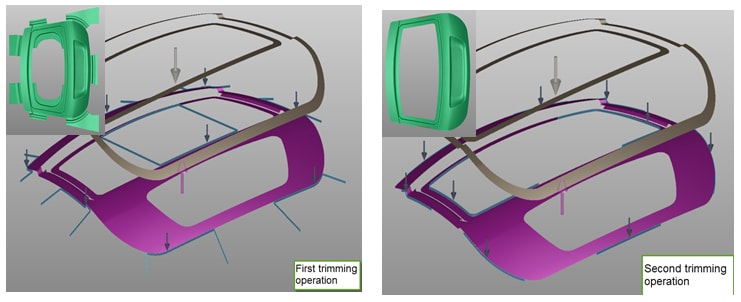
Fig. 5: Looking at the trimming operation.
Now stepping back to the draw die. Draw beads also need to be simulated correctly. In AutoForm you can close the binder with physical bead geometry which will affect the formability of the sheet metal in the areas of the beads. The bead geometry can be removed from the tools and the sheet to finish the forming with our line beads, then the physical bead shape can be reapplied into the panel at the end of the forming process for springback results. The physical bead shape is represented by a line bead during the drawing process. The solver takes into consideration the effect upon the panel of bending and unbending as if the material would be flowing through the physical bead shape. By doing this you can supply the proper bead shape to your engineers to be used in their die designs. The correct bead shape will influence the “draw in” of the panel, the necessary forces to set the bead shape, as well as the formability results. We are confident that this defined process works well in simulation and will also greatly influence the springback results.
What about lubrication? Should we consider this as an important factor playing into the amount of springback? The answer is yes of course. The coefficient of friction is dictated by the type and amount of lubrication applied in the press line. Again if something has an influence on springback then it should be properly considered during simulation. The amount of friction will come into play with the amount of material flow where the sheet is in contact with tools. This is particularly important where the material flows through a radius or is clamped on both sides by a binder or pad. You should know what the values are for the coefficient of friction for your lubrication needs whether the information comes from your lube supplier or testing your tool and sheet materials.
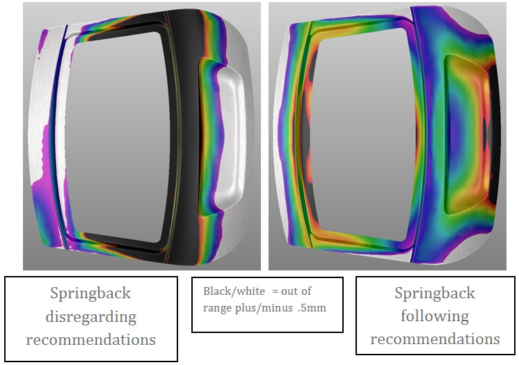
Fig. 6: The desired result.
Conclusion
As you can see there are many factors that contribute to creating springback. Controlling what you can is not as difficult as you may think either. All of the above can be done in a very short amount of time using simulation to assist in reducing the effort to correct springback during the tryout phase. This process will provide your Design Engineers a very good start to a proven process. You will also layout a stabile foundation for strategizing how to morph tools to correct springback. (A different topic for a different discussion) I will not try to tell you that you will never recut a tool by applying simulation as there are many influences that affect springback outside of the simulation process. However if you can reduce the recuts to a minimum you will certainly save a lot of money. And from time to time if everything in the entire process comes into alignment, you may see the “one hit wonder”!
New readers, don’t forget to sign up to our blog to stay informed about future post. We’ll never send you any marketing emails, just a once per month reminder from FormingWorld featuring our top post.


?")


