Springback is a phenomenon we just can’t avoid in sheet metal forming. Depending on the part geometry, material and die face design, we’ll observe more or less springback in a formed part, and that undesired shape has to be somehow corrected to bring the part within the specified tolerances. Prior to correcting (morphing) tooling surfaces to bring springback into compliance, it is important to control springback: minimize its magnitude and ensure its repeatability. Correction of tooling surfaces should be minimized in order not to significantly change the forming process itself, and in order to minimize surface quality distortions.
General Motors was one of the pioneers in using Finite Element Analysis (FEA) to predict the forming behavior of sheet metal. In the early days, engineers were happy with simulations for predicting the forming behavior, showing wrinkling tendencies and possible splits. With time, advances in simulation technology, and the evolution of hardware, allowed simulation to accommodate complex material and friction models, press kinematics, and realistic forming conditions, as well as higher resolution of the sheet metal in simulation; these advances enabled increasingly accurate simulation outcomes, which also encompassed more than just formability – tonnage, surface quality, springback, repeatability, compensation, etc. These technological advances have been timely and essential to meeting the challenge of working with newer and increasingly complex material grades, as well as increasingly complex product designs.
It soon became routine for GM engineers to go beyond draw simulations, and to develop and simulate the full process layout: secondary forms and trims, trim line development, springback between operations, etc. Intermediate springback was recognized to be very important to understand sheet behavior, positioning, and nesting as it moved from one station to the next.
The path to an “ideal simulation” that represents the full operational layout is a gradual and progressive process and aims at first to minimize springback. That is achieved by finding the best geometry for the addenda, together with a process that will produce less overall springback.
GM engineers will introduce datums in simulation to balance the springback in a way that reduces the shape change that needs to be introduced in the draw die station for the purpose of compensation. These datum studies are made incrementally. The first set of datums used by GM in simulation are the “surface datums”.

The sequence towards an “ideal simulation”
User runs a free springback and checks which points (normally 3) are stable and within springback tolerance (normally +/-0.5mm). Several simulations are run with these datums in car position, with the intent of establishing a stable part shape in this position, removing the rigid body motion.
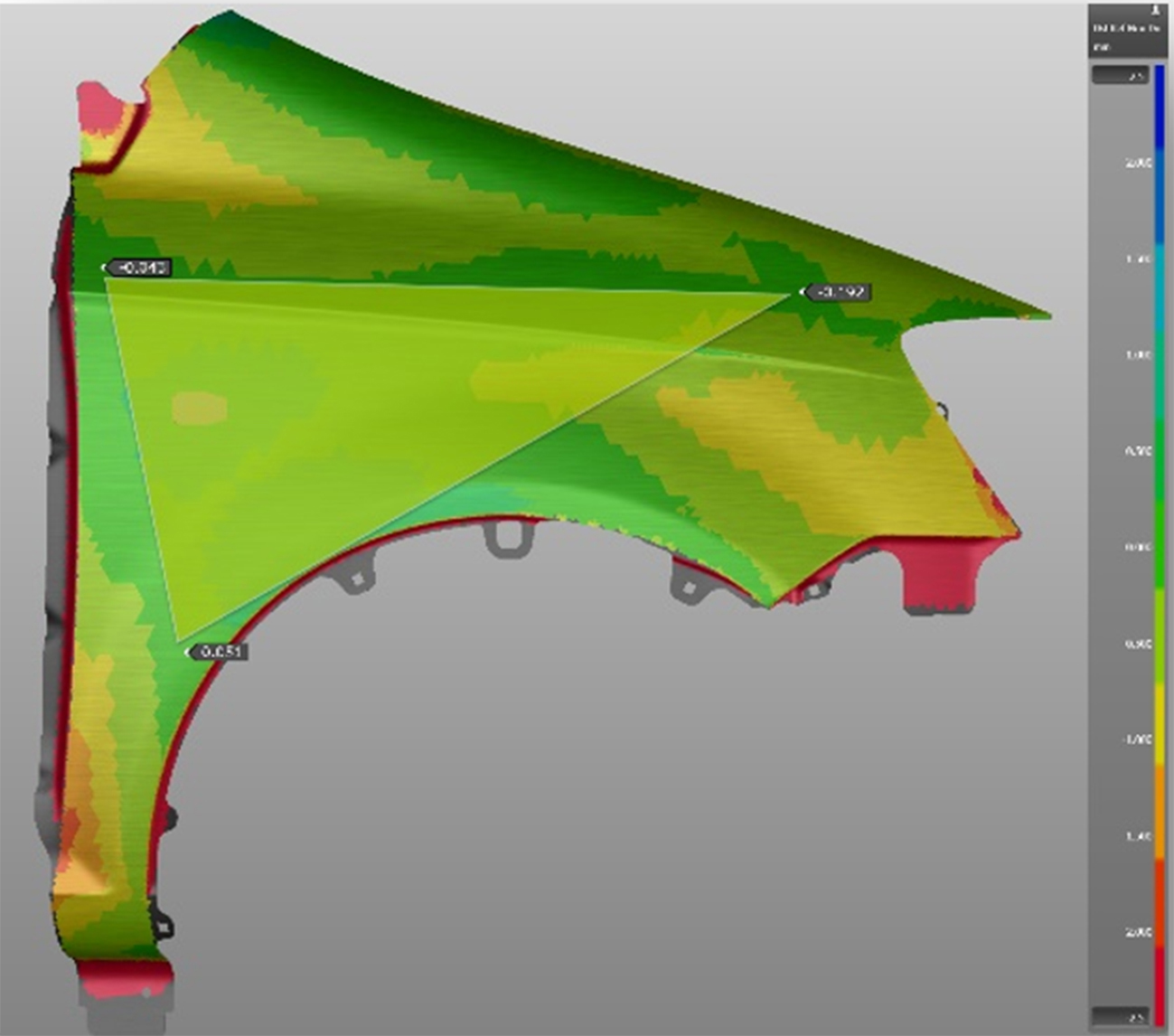
Defining 3 stable points within tolerance
When the user has found these stable “surface datums”, he can now define the “flange datums”. This new set of datums are typically defined close to the actual production datums (“panel qualification” datums) and are used to facilitate compensation of flange areas without affecting the Class A regions.
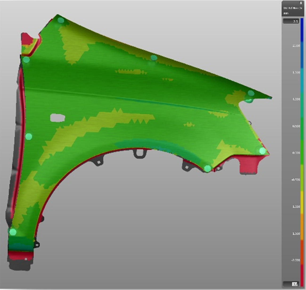
Defining the flange datums
Equally important is to check the robustness of the process – that the simulation outcomes are “repeatable” despite expected and minor variations in material, thickness, forces, etc. An unstable process will result in a very difficult compensation strategy, if at all possible.
With a stable process and the compensation map defined, based on the “flange datums”, GM engineers will include all the operations in their simulation model, including what happens with the sprung panel between operations. Pads are closed and possible interferences on trim and pierce operations are checked and potentially corrected.
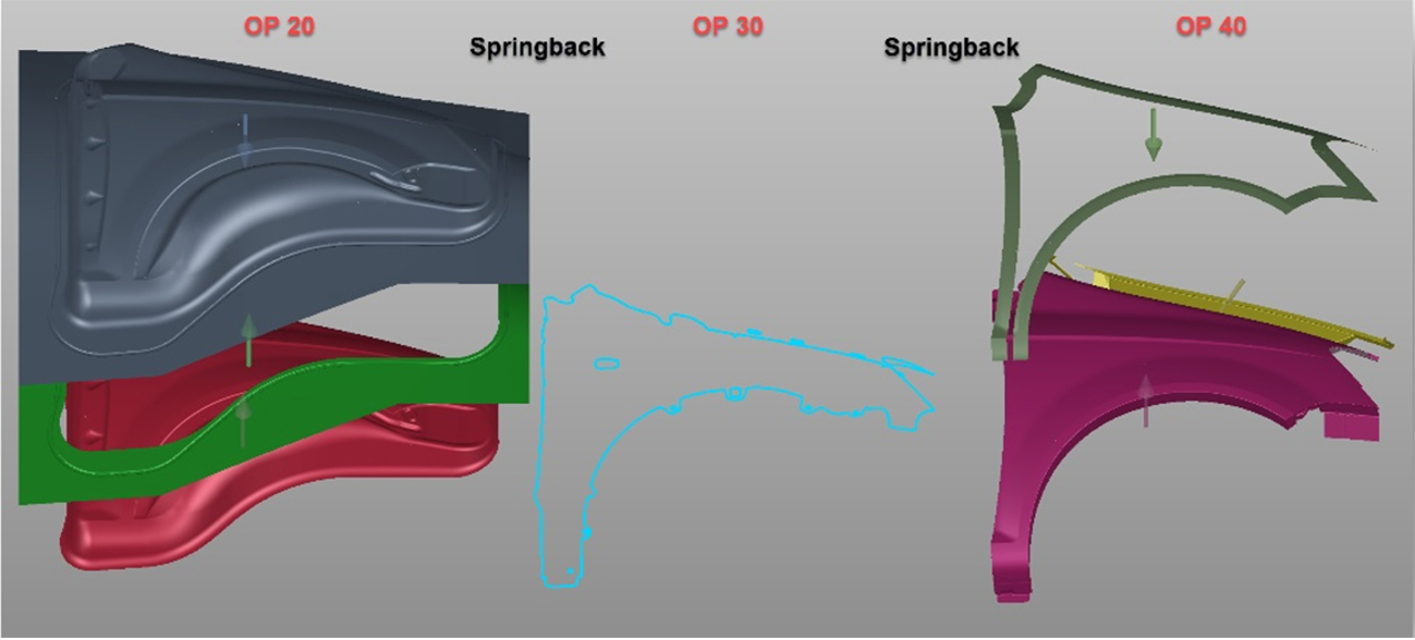
Complete simulation setup, including springback between stations
This simulation is used to generate the compensation map, which is then applied towards morphing of selected tool surfaces. Morphed surfaces are introduced into the full process simulation, and the resulting springback is checked using the “panel qualification” datums; morphing and validation typically goes through a few iterations until the final panel shape is sufficiently validated against dimensional requirements.

The sequence towards a “complete simulation”
Initially, such complex “full process” simulations were handled by a small team of advanced specialists. Over time, GM developed a standardized procedure for this, empowering their wider, global formability teams to accomplish the needed engineering tasks in a consistent fashion towards high quality engineering deliverables.
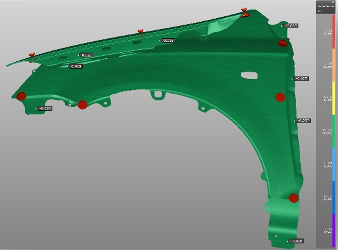
Defining the flange datums


