
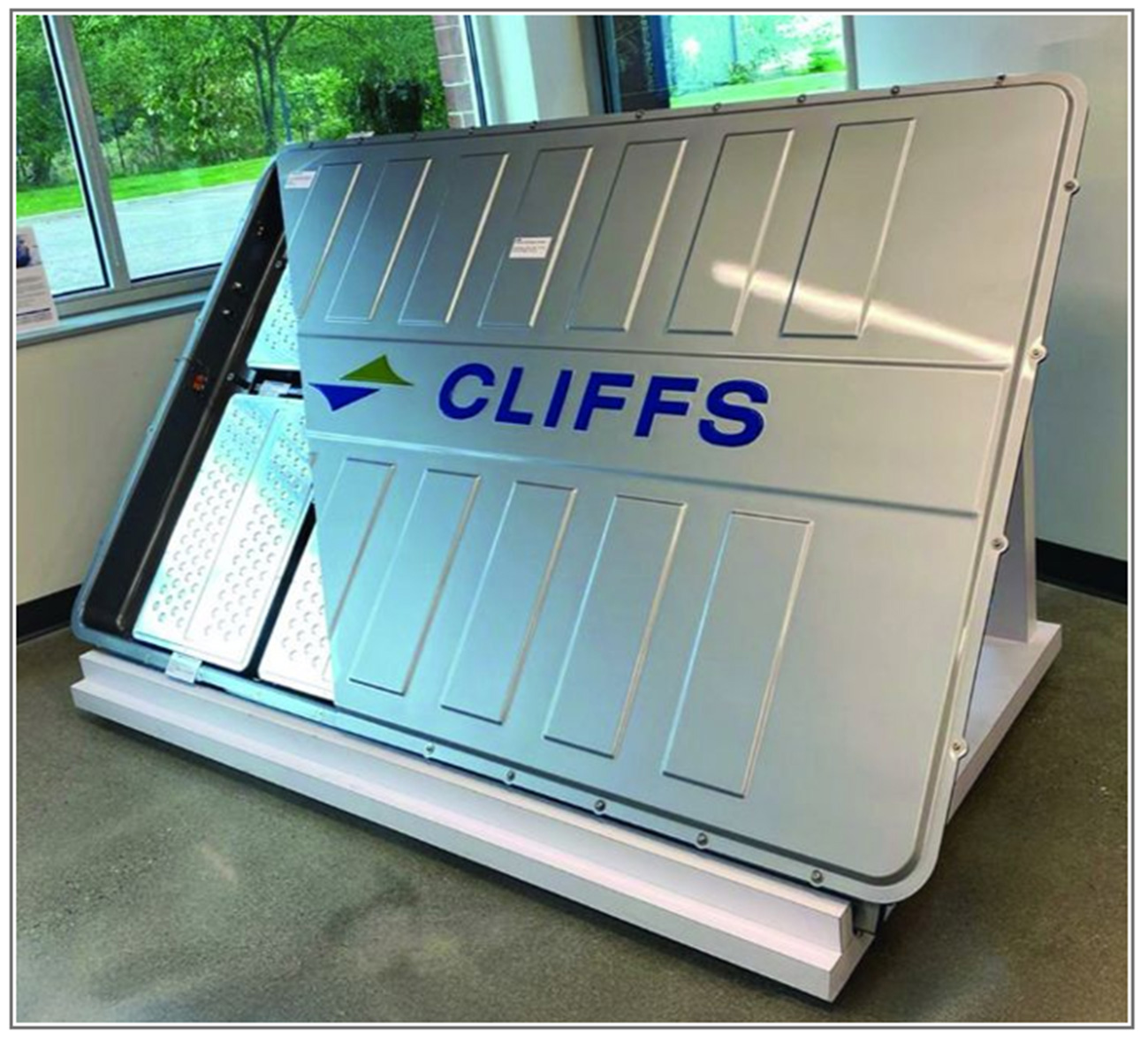
Simulation demonstrates the feasibility of creating a tailor-welded blank for an EV battery tray, combining AHSS and lower-strength steel to develop unique blank configurations.
A battery pack, which includes the housing, battery cells and harness, battery management system, and cooling systems, typically represents 10 to 20% of the overall weight of an electric vehicle (EV). Although this depends on the battery technology selected and the energy-capacity requirements of each vehicle model, weight savings can clearly be achieved through the design of the battery enclosure.
The choice of material, gauge, and manufacturing process for enclosure and assembly components presents opportunities to reduce both weight and cost, while still protecting the battery itself.
In constructing battery trays, vehicle manufacturers have used a variety of material and manufacturing-process combinations, with steel and aluminum dominating applications for top-cover and bottom-tray components. Because aluminum battery trays produced through extrusion, casting, and sheet forming are costly and difficult to manufacture, an opportunity exists for a stamped one-piece steel battery tray that eliminates the need for additional under-battery floor protection.
Cleveland-Cliffs Inc. has developed proposals for such one-piece battery trays using tailor-welded blanks (TWB) that combine advanced high-strength steel (AHSS) with formable lower-strength grades of steel. Isaac Luther and Dawn Stubleski of TWB Co. (Monroe, MI) provided tailor-welded blank samples for the feasibility studies, and QMC-EMI (Livonia, MI,) manufactured the prototypes.
Lower Strength in Corners
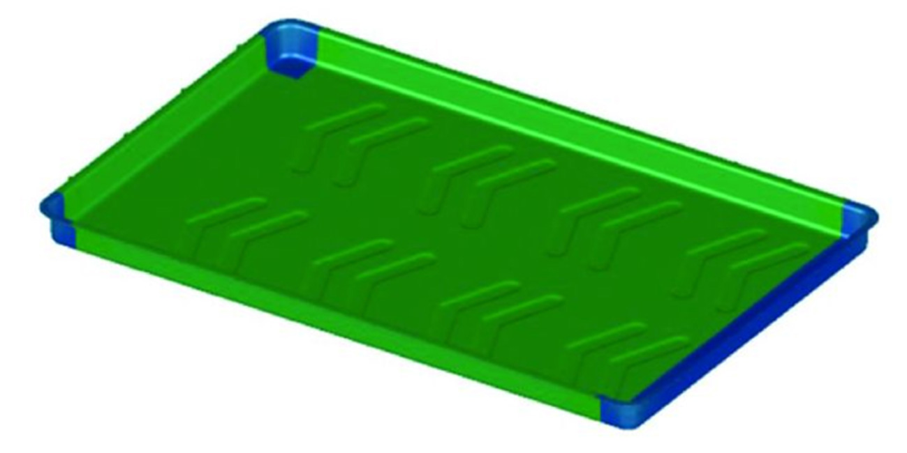
Fig. 1: The initial tailor-welded blank design for the stamped tray featured lower-strength, more-formable steel in the front and two rear corners of the blank. Blue and green areas represent different mild steels on the tailor-welded blank.
In the initial TWB tray design, the front and two rear corners of the blank consisted of lower-strength, more-formable steel (Fig. 1). The remainder of the blank, including the front wall and the two sidewalls of the tray, was stamped from AHSS (M1500 or M1700).
Cleveland-Cliffs engineers conducted multiple rounds of engineering and simulation to assess feasibility, using AutoForm software for material selection and TWB design along with structural analysis simulations. These analyses confirmed that the full battery enclosure with the TWB tray would exceed ballistic underfloor-impact and side-pole crash requirements.
However, AutoForm simulation of this initial TWB stamping design revealed severe springback and twisting of the material after the stamped tray was released from the die. Physical prototyping later confirmed these results. To meet stringent leak-test requirements for battery enclosures, the tray flange must exhibit a flatness variation of no more than ±1.5 mm across its entire length. Because of the severe springback, this requirement could not be achieved.
Hashtag-Shaped TWB
Through further TWB design optimization, Cleveland-Cliffs engineers developed a configuration with AHSS located in the flat bottom of the tray and mild steel surrounding it, including the sidewalls and tray corners, forming a hashtag-shaped (#) configuration (Fig. 2). The AHSS provides the required underfloor protection. Because this section undergoes very little deformation during stamping, weld-line movement remains minimal. This helps maintain the integrity of the laser-weld line and allows it to remain leakproof.
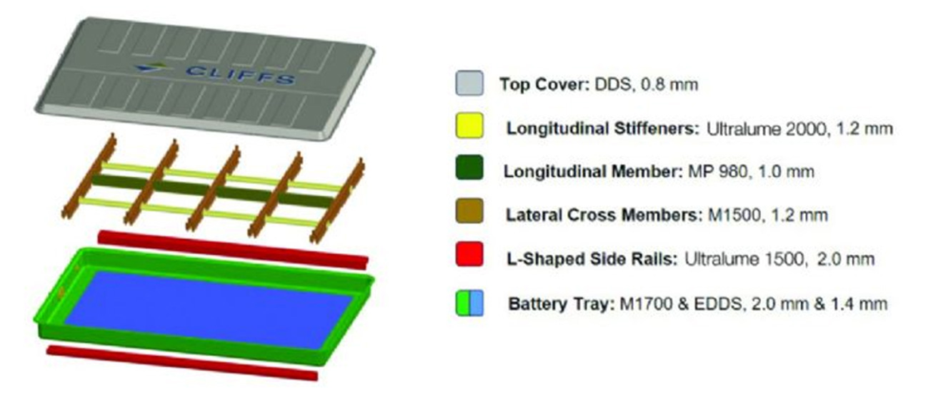
Fig. 2: The validated Cleveland-Cliffs electric-vehicle battery enclosure includes advanced high-strength steel (M1700) in the bottom of the tray (blue) and a lower-strength steel in the sections that require severe deformation (green)
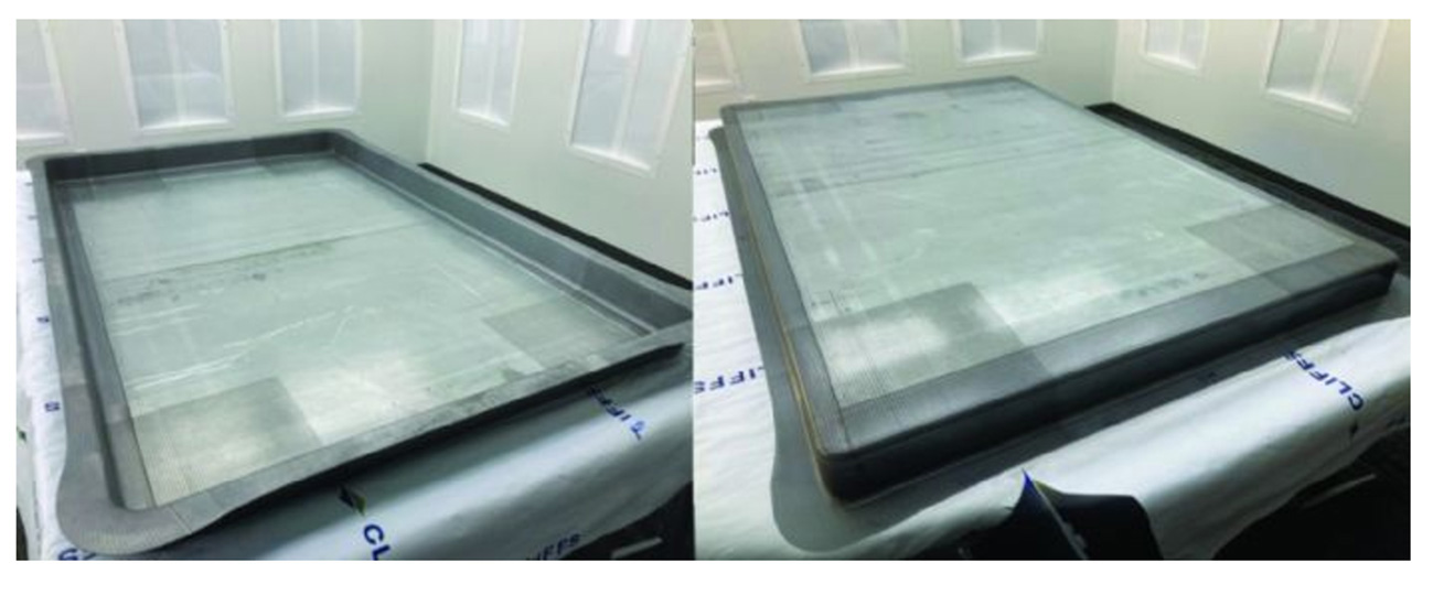
Fig. 3: Cold-stamped tray with hashtag-shaped (#) TWB
AutoForm simulation and subsequent physical stamping trials confirmed minimal springback in the tray stamped in one hit from the newly designed TWB. The stamping met flange flatness and other dimensional requirements, with no splits or wrinkles. Figs. 4 and 5 show draw-in and thinning contour maps from AutoForm simulations used to correlate with the physical trials.
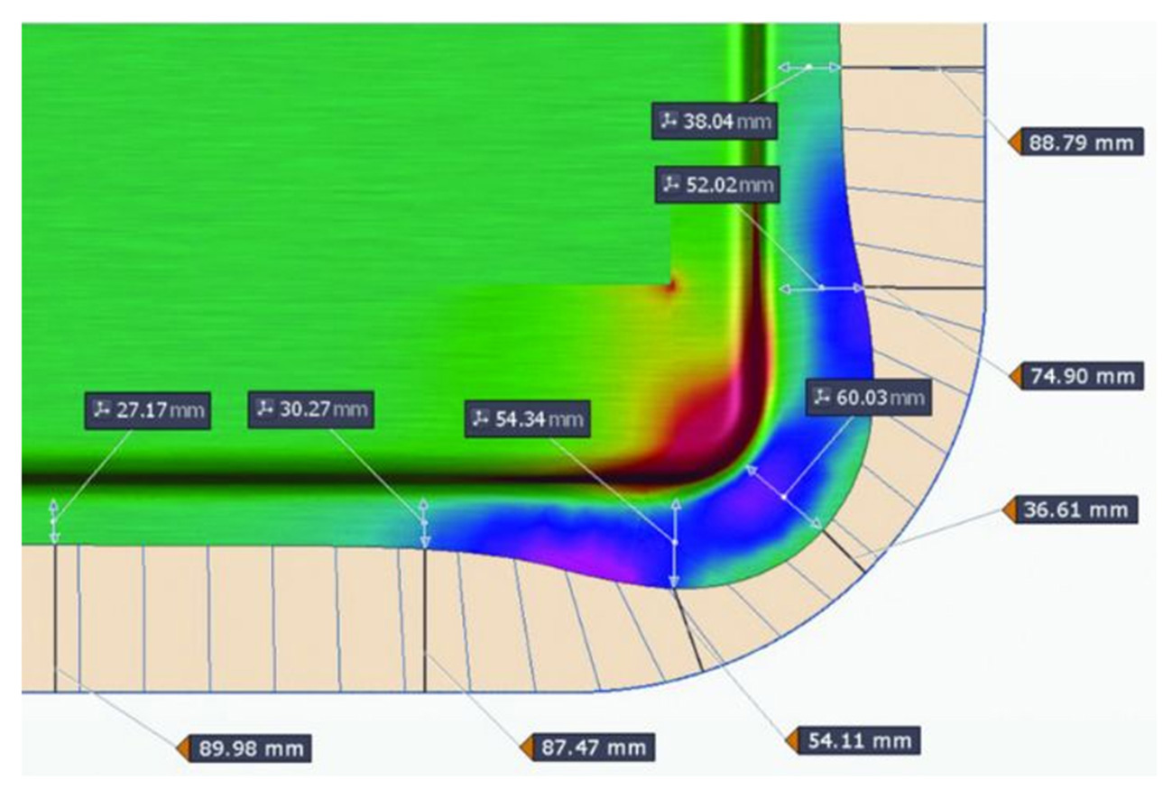
Fig. 4: Draw-in map at one corner of the stamped # TWB
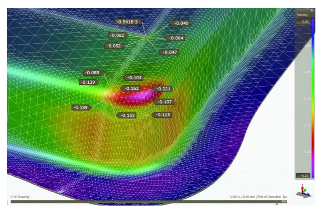
Fig. 5: Thinning map at the same corner as Fig. 4
Mission Accomplished
Fig. 6 shows ARGUS strain analysis and the forming limit diagram from the tryout panel engineered using AutoForm software. All points identified on the panel fall under the forming limit curve, indicating no risk of splitting. Simulation of the revised Cleveland-Cliffs blank design, supported by real-world forming results, demonstrated success. Both simulation and forming confirmed minimal springback of the tray, with the one-hit stamped battery tray meeting flange flatness and other dimensional requirements without splits or wrinkles.
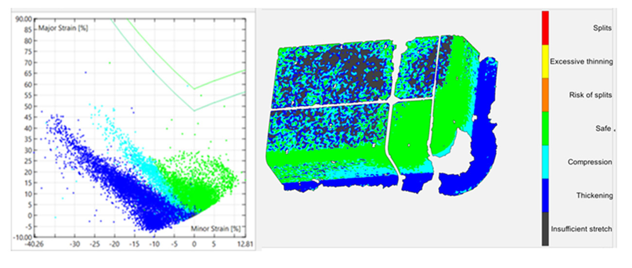
Fig. 6: ARGUS strain map and forming limit diagram
The battery tray, a critical component of the full EV battery enclosure, plays a major role in maintaining the safety and integrity of the battery package while also offering a valuable opportunity for weight and cost savings. By taking advantage of this innovative design, supported by Cleveland-Cliffs’ material expertise and AutoForm’s simulation capability, the project team completed the bill of materials for the proposed full battery enclosure and produced full-scale prototypes.
This article was coauthored by Feng Zhu, Jimmy Zhang, Sobhan Nazari, John Makrygiannis, Miao Yu, George Elengikal and Yu-Wei Wang, Research and Innovation Center-Advanced Engineering, Cleveland-Cliffs Inc., Cleveland, OH; and Kidambi Kannan and Don Hahn, AutoForm Engineering USA, Inc., Troy, MI.
Reference: Stamping a One-Piece TWB Battery Tray | MetalForming Magazine Article
Industry-Related Terms: Blank, Die, Flange, Forming, Gauge, Model, Forming
View Glossary of Metalforming Terms


?")


