
Focusing solely on accuracy can lead to losing sight of reality and driving up costs.
Throughout our daily lives, we often hear about the precision and accuracy of various products and services. While aiming for accuracy is important, it shouldn’t be the only goal. Pursuing “accuracy” from the very beginning of a design process could be a waste of time and effort. When starting a project or making decisions about how to quote a job, there may not be enough time for such precision. This might seem counterintuitive to engineers who typically demand measurements to the fourth decimal place, exact specifications, and finite limits for all metrics. However, to achieve such precision, we must be pragmatic. Meeting exact requirements is just one piece of the puzzle. Our ultimate goal is to sell our product or service successfully.
What matters most is making solid engineering decisions early on, when they are most needed. This approach allows for our design process to be productive while producing accurate results.
This article focuses on tooling geometry creation, which involves creating the surfaces and curves necessary to define the tool surface for use in simulation. In this context, “accuracy” refers to a couple different things. First and foremost, it means that the surface position and topology are in the correct position and orientation. Secondly, it could refer to controlling the connection between surfaces to a specific threshold. However, at this point in the development, the accuracy of surface connections is not the primary focus; that topic will be addressed later on.
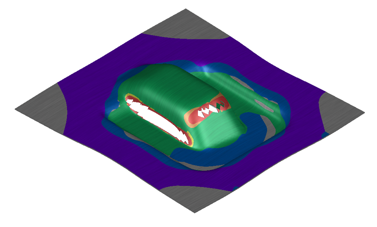
Figure 1: Formability of New Part Design
For a new project, we need to design a process for producing a part which is similar to several past jobs, but with some differences that we know could cause problems in production. Our goal is to make it better, but we need to confirm our countermeasure ideas before investing too much time and effort in a design that may not work or be robust. This is where we need to step away from “accuracy” and focus on exploring various processes and tool shapes quickly to allow the correct analysis to be done.
We can’t rely on a generic CAD software for this purpose, as we need to evaluate robustness at an early stage to avoid major changes later on. Instead, we need to see initial results from simulation to inform our design decisions. For example, Figure 1 shows that the part differences are significant enough that a single draw causes too much splitting, and minor process adjustments won’t solve the issue. The expected cracking in certain areas matches our current production problem zones on a similar model.
Our first idea is to design and set up an additional pre-draw to more evenly stretch the material, then form it to the final shape in the second forming operation. However, we need to estimate how much we must expand the material, which is still a guess at this point since we haven’t evaluated springback improvements, wrinkles, or blank utilization. But we don’t need machining quality surfaces or to spend hours in CAD on multiple versions to prove our idea. What we need is proof of concept for this process change. Accuracy is only valuable when it’s truly needed, and right now we’re just looking to modify the surfaces we already have.
So let’s explore one way to do this.
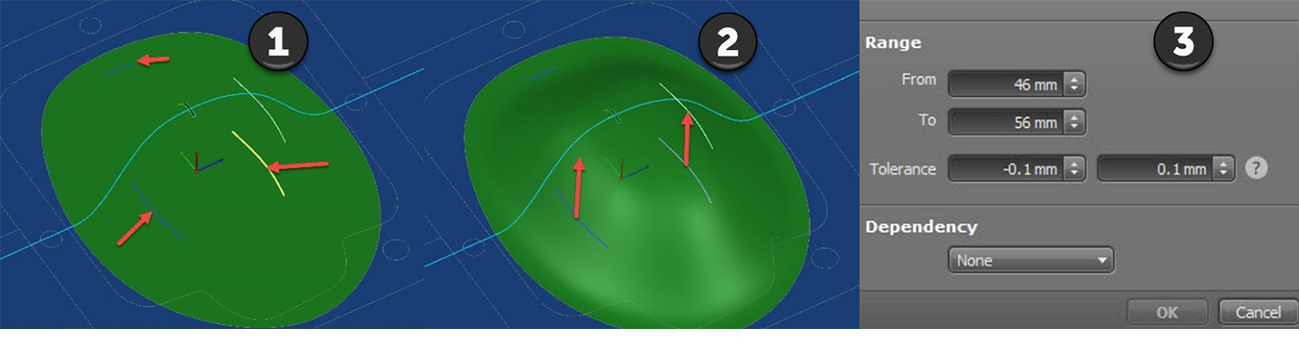
Figure 2: Steps to setup a flexible construction for investigation
In Figure 2, we can see some graphics that illustrate the process. Using a morphing technique on the surface, which is controlled by only a few curves (#1 & #2), we can rapidly generate a range of results that align with our concept for the initial draw. This enables us to confirm that our idea is effective before spending time creating the surfaces in CAD. Step #3 in Figure 2 shows how these modifications can be given a range, allowing multiple simulation results to be automatically calculated and analyzed for an even more optimized solution.
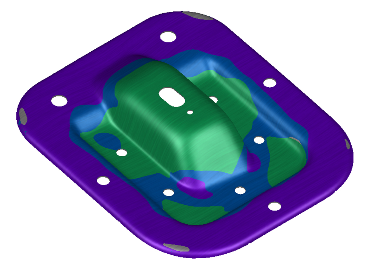
Figure 3: Formability – splitting resolved
Looking at Figure 3, we can see that although the approach shows promise, we still haven’t reached our target condition. We’ve only improved the problem. Now, we need to evaluate other criteria such as wrinkles, springback, and blank utilization in our process.
At this point, it would be best to utilize available software tools to automatically generate an optimized shape as we evaluate other quality criteria. You can review articles at FormingWorld.com for insights on Robustness and Process Optimization, and learn about systematic methods for improving your process.
It’s important to remember that “accuracy” or “high quality” may not necessarily mean “value” for your current goal. Use every tool effectively for its intended purpose and strength.
Do you think this example is too simplistic? Does it undervalue the work we do as process design engineers? Stamping is a complex system that involves many disciplines of physics and engineering. We may not be masters of all these fields, but we know how to leverage our experience and use the available tools to get the job done as best we can. This simple story is just one example of the potential value we can unlock by introducing new methods and software tools into our development process.
We’d love to hear your feedback, so please share any thoughts you have on this topic. You can find step-by-step examples for applying these techniques on the AutoForm-ServiceCenter for several different morph methods. And, feel free to contact your local AutoForm office for technical or sales support.


?")


