
 Seoyon-Top-Metal Co., Ltd. is a professional manufacturer of press die tools for domestic and global car makers including HKMC, Daimler, BMW, VW, and GM. Established in 1987, they are officially registered as a supplier and are in constant production with the best professional toolmaking staff and facilities in Korea. They are continuously developing press die tool manufacturing technology based on their experience and know-how in manufacturing various types of die tools including car body outers, inners, and aluminum.
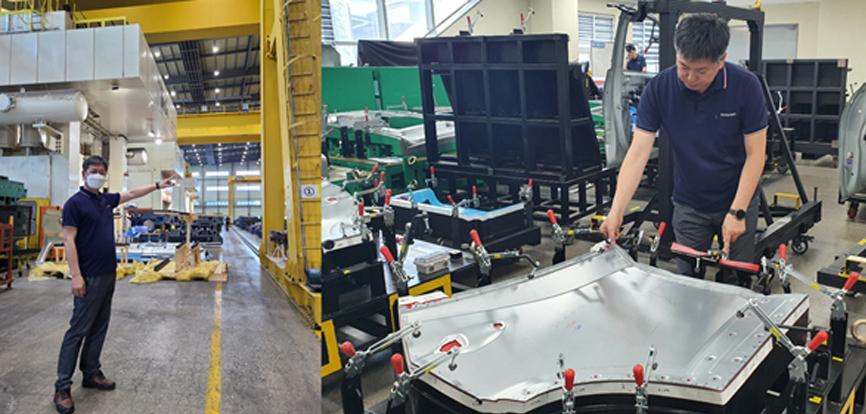
Fig. 1: The CAE team leader checks out the T/O & QC room
Seoyon-Top-Metal, a longtime user of AutoForm, has conducted many studies with high reliability through the software. In particular, the CAE team has been strengthened with extensive experience related to T/O in 2019, and conditions that require actual such as the accuracy footprint are continuously checked, verified, and applied. Now, accuracy has increased by more than 30% and the workload in T/O has been greatly reduced.
Moreover, the initial quality of Seoyon-Top-Metal’s recent aluminum panel front door outer project was over 85%, and the steel panel rear door outer received a high score of over 95% in the initial quality. Now, they’ll tell us about the conditions that led to such improvements.
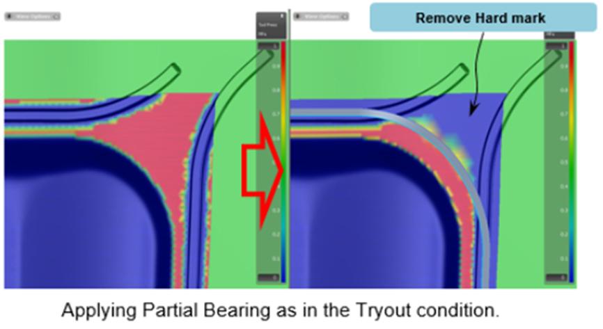
Fig. 2: Applying partial bearing as in the tryout condition
In order to obtain the same result in reality as modeled in AutoForm, the most basic element is to ensure a similar draw-in. The binder bearing condition can help minimize the time required for bead modification in the initial T/O and for the draw-in trend to proceed similarly to the Sims result. It is very simple to use AutoForm’s “partial bearing” function and specify only the area of concern to make the matching conditions the same. Depending on the binder bearing conditions, there is a difference in the restraining force of the bead. For projects with high inflows, the difference is obvious and trends can be different. In the above figure, partial bearing is defined to remove the hard spot on the outside of the bead.
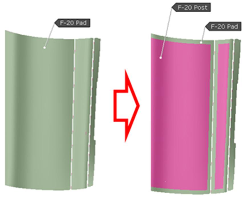
Fig. 3: Applying pad relief as in the tryout condition
And, as the part that takes the most time and effort, there are two conditions for predicting and improving the problem in advance of panel deformation during the forming process. The more easily set condition is pad relief. With little effect on formability, it is not applied at the beginning of engineering, but it is absolutely necessary for correct springback analysis. For each process, in order to avoid overloading the radius area of the sheet, the radius shape and areas that do not need to be closed during the process are relieved. The radius shape can be removed from the tool by simply using the “remove concave radii” function. When the work is completed in this way, any pad force that appears too high in simulation can be prevented. In other words, the radius shape prevents additional forming during pad closing, reducing panel deformation as much as possible.
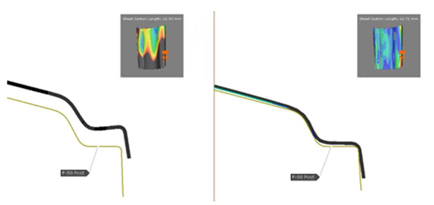
Fig. 4: Locating condition improvement with drawshell compensation
Another condition that takes a lot of time and effort is optimizing the locating condition of the sheet on the secondary operation. The locating condition between processes is also important to prevent the possibility of panel deformation. Projects sensitive to springback such as aluminum need to be improved by compensating the next operation’s tools as the shape of the panel in the previous process. This can be solved using AutoForm drawshell compensation. Following, springback and Sigma robustness are analyzed to determine the possibility of compensation.
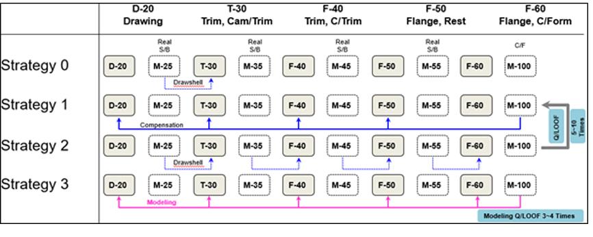
Fig. 5: Compensation strategy for door OTR
With reliable results, this project was compensated as shown in the figure above. Based on the last springback, the tools of all operations were compensated, the locating condition after compensation was analyzed, and drawshell compensation was performed for affected operations.
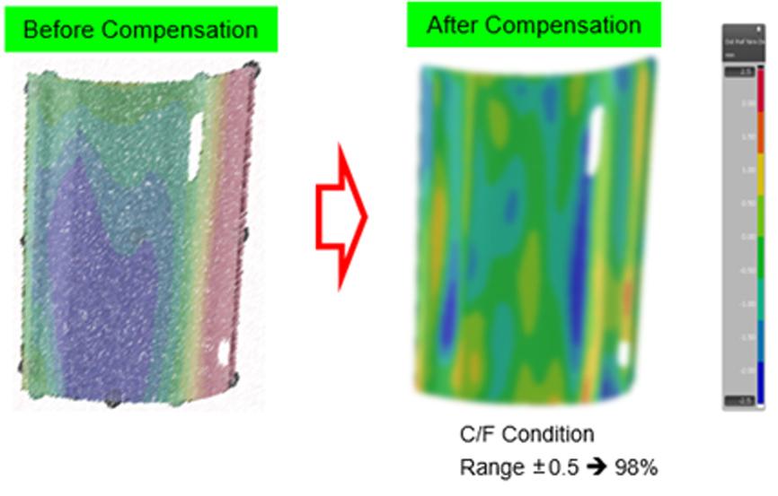
Fig. 6: Springback result of final validation after compensation
Good results were obtained, as shown in the Fig. 6, while minimizing the deformation between processes through many iterations, and we were able to achieve the same results in the initial T/O.
When we first started the aluminum panel project, we experienced many failures. There was a difference between AutoForm and reality, and it took a lot of time in the T/O to resolve it. In response, problems that could cause panel deformation were identified and improved in advance of the engineering phase to compensate for the problem, and good results were obtained.
Summary
By improving unwanted deformation during the forming process in advance, reliability and accuracy were increased so that the results of AutoForm and T/O were the same. As a result, the initial T/O score of the rear door outer steel panel and front door outer aluminum panel in our latest achieved over 85% and 95%, respectively. The engineering phase required more time and effort, but the amount of work required to fix T/O was reduced by more than 50%.


?")


