
Today’s car bodies are made of some 150 – 200 parts. They all have to be functional, serving their design purpose. We can distinguish external, interior panels, structural parts, etc… According to their functionality, the position in the car and to which other parts it shall be assembled with, different materials are used for different parts which have comply with acceptance criteria (surface quality, dimensional tolerances etc.) Further to all this, if we consider the different targeted market segments and the different styling and their manufacture, we can understand the necessity of establishing “standards” within companies; standards that every single supplier must comply with if they want to avoid the rejection of parts or tools, along with any penalties they might incur therefrom.
Within AutoForm all users have the possibility to load and apply “Standard” files to configure some of the input and output parameters of the simulation project file, and make sure (zeroing risk of non-compliancy) that everything responds to their customer or their own requirements.
In addition to this undisputable benefit, there is another one that comes naturally with such automatic settings: time saving. By loading a standard (at the begin of the project as well as on the fly) all parameters controlled by it are automatically loaded so the user does not have to manually check them once again, allowing the user to continue working without “interruptions”.

Fig 1. Example of thinning difference between two identical parts when Evaluation standard is changed.
Different Standards apply to different “areas” of the software
Since the “standard” file may contain information regarding a subset of parameters (for example the “press” standard establishes parameters linked to the press, such as dimensions, stroke, etc.) we can therefore distinguish different types of Standards files. Let’s quickly have an overview of the possibilities within AutoForm.
Design Standards: being used as “general project setting” through this file the user can set a large number of parameters. For example, the mesh refinement can be set, some parameters regarding the automatic addendum design for the initial feasibility analysis, as well as the creation of the tool used during simulation and also some material-related parameters (costs per kilogram and scrap value, etc.).
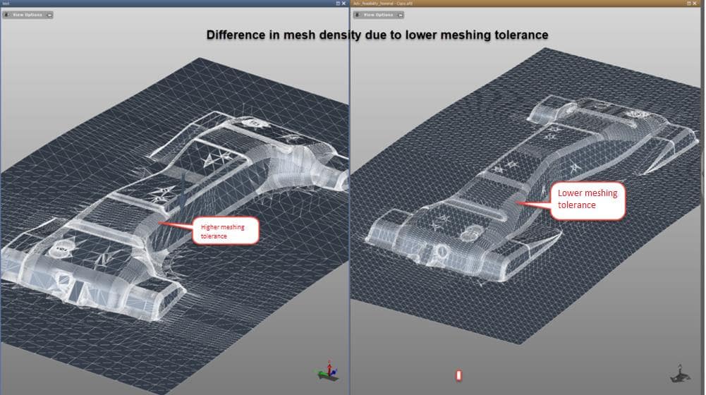
Figure 3 – Change in mesh density on identical parts due to change in meshing tolerance in Design Standard
The figure above shows the difference in size and number of the mesh elements with a different setting. Lower tolerance implies an higher accuracy on the approximation of the geometry; on the opposite, an higher tolerance means a lower accuracy in approximate the geometry. No need to mention how this setting affects calculation time and results.
Control Parameter Standards: sets the main parameters of the solver and offers control on result variables and output time steps.
Press Standards: is used to define different types of presses (dimensions, ram tonnage, typology, etc.)
Tooling Cost Standards: is for all tool cost-related configuration
Sigma Standards: defines partial or entire setup for AutoForm-Sigmaplus.
Evaluation Standards: defines the acceptance criteria (limits) of all result variables and an index of the colors and views associated with them. The definition of these “boundaries” is really important because it defines what is acceptable and what is not. It assumes a crucial role in the “visual” evaluation of the result since it defines the color of each single calculated element. As long as the user operates the software, he/she has access to the calculated value and therefore make a quantitative analysis, but when the colored map gets into tryout through a static report for instance, the colors are everything the operators can rely on, and it is fundamental that engineering and tryout “speak the same language”. Just to give you an example, Figure 4 shows Max Failure results while adopting two different scales. The red area on the right indicates very high risk of splits while on the left the risk seems to be much less but the only difference between the two parts is the upper level of the color scale (on the left it has been set to 1.2 while it is 0.8 on the right). Can you imagine what operators in tryout would think while taking a look at the results on the right? And on the left?

Figure 4 – Max failure map, comparing the difference of a max scale at 0.8 vs. 1.2
Another example could be the definition of the thinning limits. According to the material and the function the part we are simulating have in the vehicle, different thinning limits are accepted. The figure below shows the importance of setting the correct limits for rapid evaluation and to visually detect the issue within the part. As example, the figure below shows the thinning result displayed with two different acceptance criteria; with the limits set on the left the part may look acceptable with a certain risk of failure while with the limits set on the right the part is definitely not acceptable.

Figure 5 – Example of thinning difference between two identical parts when Evaluation standard is changed
Process Plan Standards: defines project data and piece cost values.
The Power of Standards for Guiding an Entire Company
As already mentioned above, a “Standard” can be either a single setting file or company-broad setting. That means that a “standard” can be in reference only to certain parameters and depend on the type of material or part for instance, or it can be “company specific” which means that all users working on that company’s simulation files will have standardized input parameters and evaluation criteria.
New standards can easily be created and utilized to automate monotonous processes or existing standards can be modified according to the users’ intention.
For a flexible and more direct handling of the files, all available standards can be grouped into one category and that entire category can be loaded at once (the user does not have to load standard files one at the time); this possibility not only allows users how to save some time but reduces the risk of loading the wrong “standards.”
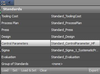
A dedicated prompt of the AutoForm GUI allows users to load standards at the beginning of the project and for all projects; actually this prompt can automatically appear (upon user setting and request) whenever a new project is created so that the check is somehow “forced” and not ignored.
While setting up the process as well as upon concluding it, when results are checked it is important also to immediately realize when, which and how project data deviates from what was established in the Standard. For this purpose, AutoForm implemented some automatic checks with the highlights of these “mismatching-parameters” in order to draw the user’s attention on it.
The possibility of setting standards in AutoForm increases and facilitates communication and knowledge transfer between different departments within a given company and also between a company and its suppliers. The loading of standards which come directly from customers empowers the job of tool and part suppliers because they are always sure that input settings and evaluation criteria are met at all times. The reports generated by suppliers, during or at the end of the engineering process, are always compliant with customer requirements. What more could you want to ensure quality?


?")


