
Cold stamped part suppliers are facing a new challenging era of ultra-high strength steel (UHSS) applications, with pressure to increase passive safety and decrease energy consumption. The challenges associated with UHSS are the result of relatively high frictional forces and a sensitivity to substantially high tool forces during the forming process. Moreover, springback effects can be significant, manifesting through wall warping, twisting, and longitudinal warping. To achieve high quality part production along with a robust process chain, process engineers need to identify the origin of springback and design the forming simulation as precisely as possible. One important contributor to securing the forming simulation quality is the digitalization of tribological conditions (such as friction conditions) based on real process conditions. In this blog post, I detail the results of a recent project by a major Tier 1 part supplier based in Japan — adopting an advanced TriboForm friction model in the forming simulation of a UHSS B-pillar.
In Japan’s press-forming industry, the common approach to weight reduction while meeting the stringent requirements for passive safety is to use a material type with a higher strength. For this reason, a recent trend is using ultra-high strength steels, having grades that go up to 980-1180 MPa tensile strength. As a result, simulations are indispensable for ensuring the formability and dimensional accuracy of the press-formed products. Building an accurate simulation using the accuracy footprint concept requires the definition of many factors like process settings, material properties, and tribological conditions (e.g., friction) based on the real forming process.
Although nowadays, process engineers can easily define process settings and examine advanced material models, they typically distance themselves from the issue of “friction”. This is mainly due to technical issues, such as the difficulty of measuring the friction coefficient (µ) accurately. In the recent past, the Japanese part supplier in question was using a constant value for the friction coefficient — which means it wasn’t describing the real frictional behavior during the forming process. Forming UHSS in particular can raise major springback issues due to high local forming forces. So the main goal of this experiment was to address the issue of “friction” and to investigate how a TriboForm friction model could further improve a digital model by replicating the real conditions a step further.
The studied parts were two B-pillars made from 1180MPa UHSS grades with a thickness of 1.2 and 1.4 mm, formed by tool steel and lubricated with a drawing oil. The major issue throughout forming was the difficulty in securing the tolerance of dimensional accuracy, particularly during the drawing process. The springback behavior became inconsistent, causing more wall warping and twisting than predicted in the simulations. This consequently incurred additional time and cost for adjustment, provoking the need for a solution.
The AutoForm software was used to make a comparison between the current simulation approach, using a fixed value of the friction coefficient (µ= 0.15) with a TriboForm friction model. Figure 1 shows the AutoForm + TriboForm modelling strategy, which is based on the real tribological system used in the forming process and considers several parameters such as tool and blank surface roughness, lubricant type and amount, pressure, velocity, temperature, and blank deformation. The tool and press shop can then refer to these values as quality control parameters during try-out and production. You can read more about TriboForm friction models in these blog posts.
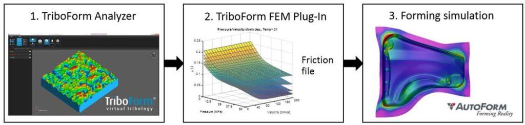
Fig. 1. Simulation approach for friction and lubrication modelling in sheet metal forming simulations
Dimensional accuracy and springback results
An external software was used to align the actual panel and the simulation results from the 1st (draw) process and to calculate the degree to which the entire surfaces match. Figure 2A shows the improved dimensional accuracy with the TriboForm friction model. For both parts, the accuracy improvement rate (%) was the same. Figure 2B shows that the bandwidth of gap decreased to Δ4mm across the entire surface — which bodes well for the consistent improvement of accuracy and production quality.
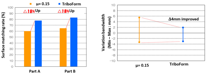
Fig. 2A) Surface matching rate improvement; B) and gap bandwidth improvement by using the TriboForm friction model plus AutoForm compared to the constant friction
Springback analysis identified longitudinal wall warping and twisting model shapes in the real panel, which can be accurately predicted using the AutoForm + TriboForm modelling approach (Figure 3). The remarkable improvement compared with using a constant value for the friction coefficient emphasizes the important role of frictional behavior in forming UHSS parts.
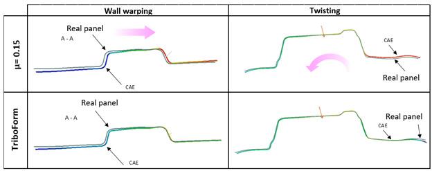
Fig. 3. Qualitative prediction capability increased for both longitudinal wall warping and twisting model shapes
Flexible and acceptable payback period of ROI
An astute manager needs to decide whether to accept or reject a new software solution based on the added benefits over a determined time period. When digitalizing, ROI assessments must consider not only labor-force adjustment and stranded costs, but also the benefits gained in terms of competitiveness, supply chain viability, and worker and capital productivity — especially given the quality of highly sensitive UHSS springback. In order to prove the benefits within an acceptable payback period, the manager can apply a step-by-step approach using a plug-in & consistent software structure. They can further set the intermediate objectives of the POC project in terms of accuracy/quality improvement and fast engineering in specific engineering activities that are not yet fully and broadly deployed. Even then, they likely will not prove the comprehensive benefits of full digitalization. Additionally, a faster engineering time will result from the increase in prediction capability by corrected friction model sensitivity.
So from this digitalization and ROI assessment investigation focused on identifying complex springback behaviors and quality improvement of the UHSS cold forming process, we have a good indicator of increased prediction capability to accept the new TriboForm friction model using the AutoForm system.
Conclusions
Based on the promising results of this evaluation — namely an improved dimensional accuracy tendency in the 1st draw process by an average of 18% and a time reduction to modify the tool by three weeks — the Japanese part supplier decided to incorporate TriboForm into their processes. The goal is to use TriboForm to deal with UHSS materials, and more specifically to understand the tribological conditions and related issues. Furthermore, this assessment is a good indicator of increased prediction capability while accounting for the real tribology system in forming simulations with AutoForm.
Feedback from users:
By reducing the errors in the estimated amount of longitudinal wall warping and twists, the modification of the draw die and the subsequent modification of the bending blade can be reduced as well, which will allow us to shorten the lead time. Additionally, TriboForm is not only going to be used for the UHSS materials but also for the conventional materials when the forming is complex and challenging; particularly when dealing with both cracks and wrinkles simultaneously.
Thank you Motoharu Namiki, from AutoForm Engineering Japan Ltd, for this great post!


?")


