
The main goal of the fourth industrial revolution, the so-called Industry 4.0, is to design and produce at a faster pace than ever before. Digitalization, Smart Factory, Digital Twin, and AI are all methods of becoming more efficient and effective along the entire process chain, from product design to mass production. Despite the increase of sheet metal stamping simulation software, the tool tryout phase still requires intensive manual labor and is reliant on the experience of those doing the work.
In fact, tool tryout represents 30% of the cost and roughly 40% of the total time required for tool engineering and manufacturing. Die spotting in particular accounts for 70-80% of the total tryout — hence the importance of greater efficiency during this step! Even a slight time reduction can translate to consistent savings in man-hours and overall costs.
To better understand what stamping process simulation software should provide to help shorten the time spent in tool tryout, we talked to Die Engineering Team Leader Matteo Valsecchi and Tool Shop Manager Marco Rota at Franci, a toolmaker located in Lecco, Italy. With over 60 years in operation, they are a die set OEM supplier for sheet metal cold formed parts, specializing in designing and manufacturing front fender die sets for the automotive industry.
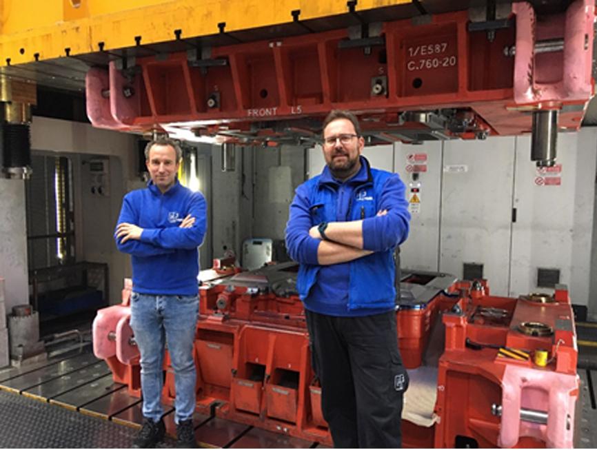
Fig. 1: (Left) Mr. Matteo Valsecchi, (Right) Mr. Marco Rota
For this article, we’ve focused on the entire spotting process to identify potential time saving measures.
“Die spotting is an essential and time-consuming step of tool tryout. Before checking the dimensional compliance of the parts, we need to guarantee that a minimum area (usually 80%) of the die is spotted to even gain access to tool buy-off. Spotting strategy is initially planned according to our experience and also to the simulation results. Once defined, it is communicated, discussed, and approved by the customer.” Mr. Valsecchi, CT Franci
One of the first questions we asked: What prerequisites are necessary to obtain an in-quality die set within an acceptable amount of time?
“A good and in-quality spotting begins with the milling of the dies. The lower the quality of the milling, the longer it is going to take to get the job done and deliver a die as per request of the OEMs.” Mr. Rota, CT Franci
Keep this statement in mind, as we’ll return to it later!
The first tools to be spotted are the drawing dies — first, the binder at the closing step (an example is shown in the image below), then the die at the bottom stroke. Usually, the punch is not spotted as it is referred to as a “master”.
Let’s examine the drawing die spotting process more closely to see how the whole procedure is carried out.
A clean blank is initially formed to binder closing. Then, the blank is blue painted in the area covered by the binder and placed under the press again. The binder closes and the shades of blue left on the blank (and the complementary areas on the die) will indicate where to spot.
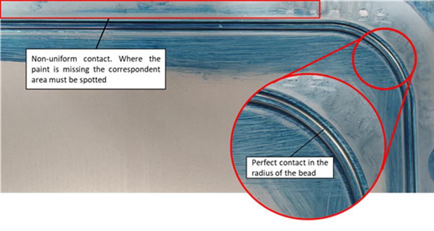
Fig. 2: Example of an incomplete binder spotting (click to enlarge)
Figure 2 shows the effect of the thickness variation combined with the flexibility of the tools and press on the binder area of the sheet. It is possible to distinguish areas where the paint is missing because it was transferred to the die during contact; in areas where the paint is still attached to the sheet, the contact with the die is partial or does not occur at all.
The areas where the contact occurs are the areas to be grinded.
The area that is always spotted is the one between the bead line and the punch opening (PO) line. The area outside the bead is in some cases spotted to consider the sheet thickening, but in other cases is simply relieved (no pressure applied). This decision is agreed on with the customer.
So, how much material should be removed? In other words, can the amount of transferred paint be translated into tens of millimeters to be removed?
“Basically, we do a qualitative analysis,” Mr. Rota said. “We start removing 0.05 millimeters at a time and then we check again; it is a trial-and-error approach, which is why it may take up to a week to spot just the binder area. Consider that the radius of the beads must also be recreated exactly as they were designed — or simulated, if you will.
“Once the binder is spotted, we move to the die. The logical procedure is pretty much the same.”
The number of man-hours needed to get the job done depends firstly on the customer’s requirements, then on the type of part and its size. Mr. Rota added:
“For outer panels, we usually try not to have contact between the die and the part area of the sheet to avoid aesthetic defects. The exception is a style line, where full contact is required. For inner panels, we must instead maintain perfect contact on the entire area so that all features that are supposed to ensure part stiffness are formed correctly.
“In addition, we need to consider whether there are splits at the bottom stroke or not. In case of splits, the contact check is performed at previous time-steps, with the scope of detecting when the crack occurs. This is always assuming that the split can actually be fixed by spotting the die. This decision can be adopted prior to customer’s approval.”
Interestingly, Mr. Rota stated it takes much longer to spot a die for an inner panel than for an outer panel.
“For the cutting and flanging dies, they definitely take longer to spot. In the case of trimming dies, we have to spot the pad in the area adjacent to the trim lines, while for the flanging tools, we spot the pad in the area adjacent to the flange.” The contact on those areas must be perfect as no movement of the sheet is allowed; otherwise, burr may occur (where the sheet is not cut but torn) when cutting the sheet.
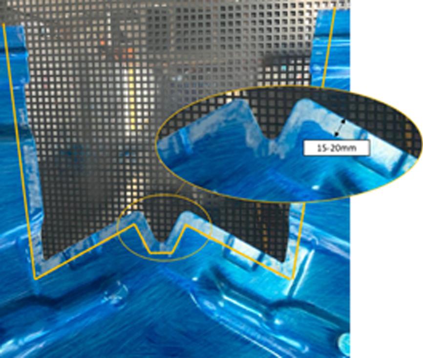
Fig. 3: Spotting area of the trimming tool pad (inner panel) (click to enlarge)
How large is the spotted area? “It depends whether we are talking about an inner or outer panel. For inner panels, we usually have a pad width of 15 to 20mm; for outer panels, the pad needs to have a larger area, usually 30mm width, in order to avoid surface defects generated by high pressure applied with the closing of the pad.”
Figures 3 and 4 show the difference between the spotted pad area in the case of an inner and outer panel.
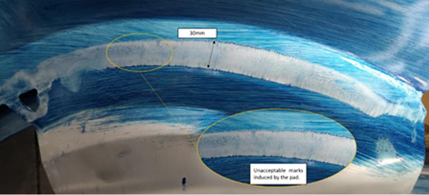
Fig. 4: Spotting area of the trimming tool pad (outer panel) (click to enlarge)
In Figure 4, you notice that the pad leaves some unacceptable marks on the sheet.
In the case of flanging tools, the area of the pad is always larger (30mm or more). This is partially due to higher operating flanging forces, which require a higher pressure on the pad to avoid any possible movement and distortion, especially with the use of cam.
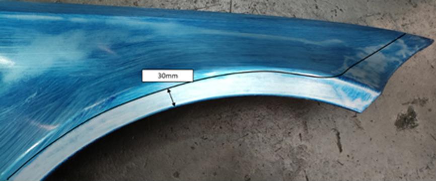
Fig. 5: Spotting area of the flanging tool pad (click to enlarge)
Figure 5 shows an example of spotting on a fender wheel and front lamp area. The pad must not leave any marks on these areas or the final quality will not be acceptable. To safeguard against distortion, the area spotted on the front lamp is a bit larger than 30mm. “When this is the solution that we need to adopt, we have to consult with the customer before we put it in place,” Mr. Rota asserted.
Naturally, this artisanal process requires a lot of meticulous manual work. Spotting a die set (four operations) may require four to five months, and even longer in some cases.
Now that the process is quite clear, the question is: how can virtual spotting reduce manual work? In addition, which process simulation results can be transferred to the milled surfaces, and how, while considering the constraints due to milling machine tolerances and setup of the simulation?
“A good and in-quality spotting begins with the milling of the dies,” Mr. Rota explained at the very beginning of our chat. So, what process is in place to prepare the surfaces for milling?
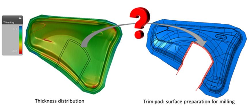
Fig. 6: Simulated thickness variation data used in surface preparation for milling
“According to the adopted strategy, we apply an offset (over-material) to the surfaces involved in the spotting directly to the CAD nominal surfaces,” Mr. Valsecchi stated. “Unfortunately, the offset cannot be constant on the spotted areas as it must take into consideration the thickness variation. An automatic procedure that transfers the thickness variation directly to the CAD surfaces would be ideal to shorten the time required for spotting, even though we have to consider the final quality of the surfaces we send to the milling machine.”
What would be the best way to transfer the thickness variation to the tool surfaces so that the manual spotting is reduced to the minimum?
We will be tackling this issue in an upcoming article dedicated to virtual spotting.
What’s your opinion on it? Please share your thoughts, we would love to hear from you.


?")


