
In the automotive industry, there is a constant tendency to find increasingly lighter and safer vehicles. For this reason, the materials used in the manufacturing process of a car demand specific characteristics to satisfy this need.
For that reason, Grupo Segura, a leading company dedicated to the design, development, and manufacturing of cold stamped metallic components for automobiles, set themselves the objective of researching and developing alternative solutions to the hot stamped applications, taking the advantage of the new generation of Advanced High Strength Steels (AHSS 3rd Generation).
The objective was to be able to cope future demand from the OEMs and gain expertise and experience of AHSS 3rd Generation industrial production. AutoForm and ArcelorMittal collaborated in the project along with Grupo Segura.
Steelgrades selected were Fortiform®1050+EG and Fortiform®980+GI. ArcelorMittal carried out material characterization and determined dedicated AutoForm forming simulation datacard. Friction coefficient was also proposed considering the coating, type and quantity of lubricants.
The aim of this project is to reproduce a part currently in production (Figure 1) but made with AHSS 3rd Generation Fortiform®. The assessment used a reinforcement floor die-tool which was originally engineered for DP600+GI (1.50 mm). The stamping process consists of a draw operation and trim operations. The draw operation transforms the flat blank into the desired shape and while the trim operations remove the excess of material.
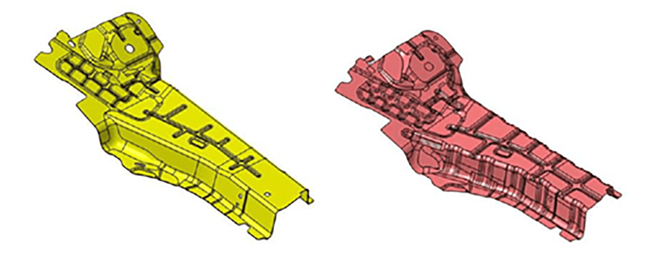
Figure 1: Reinforcement floor die-tool performed for DP600+GI (on the left) and developed for Fortiform®1050+EG and Fortiform®980+GI (on the right) [Copyright Grupo Segura]
To not affect production, Grupo Segura decided to make a new set of tools for the drawing operation, but first it was necessary to simulate the process using AHSS 3rd Generation forming material datacard developed by ArcelorMittal. This was one of the most important steps of the project.
After running several simulations, it was clear the necessity to increase the binder force due to higher mechanical characteristics compared to reference. It was also necessary to increase the drawing height and the beads restraining forces to achieve an optimal balance between a correct stretching of the material (reaching its plastic deformation) and a correct material inflow avoiding any wrinkle formation. Minor geometry changes were applied to facilitate formability and avoid wrinkles. Stiffeners were also added to compensate for springback deviations.
Here, the simulation of the process with AHSS 3rd Generation Fortiform® was even more vital than usual to predict and prevent any problem that may occur in reality and possibly not even solvable once the tool is machined.
For the tool redesign we adopted a systematic approach. This means that at the beginning we focused on the conceptual shape of the drawing die rather than the quality of the surfaces optimizing the size and position of new gainers, radii and size of the beads and other elements that would result in having the drawn sheet as close as possible to the nominal shape (reduced springback) and ensure compensability.
The systematic approach (in place of the well-known trial-and-error approach) allowed us to focus also on the optimization of the size of the blank to reduce the quantity of material and the costs related to it. The adoption of this approach allowed us to speed up the whole design process as we could consider many aspects at the same time
Before starting to look for the best compensation strategy and achieve springback results within tolerance margins, we studied the robustness or stability of the process. This is something essential before starting with the compensation of the tools. If the process is sensitive to noise variables (not controllable) as well as lubrication, blank positioning, or material properties, among others, it will not be possible to have a constant and consistent springback deviation and therefore an appropriate correction cannot be applied for all possible scenarios.
To better understand the concept, look at the example of Figure 2, in which we see that applying the conventional engineering approach the springback deviation in the nominal simulation is 2.8mm but, by checking the stability of the process (we call it also SMART Engineering approach), we see that the deviation between the maximum and minimum value is 2mm.
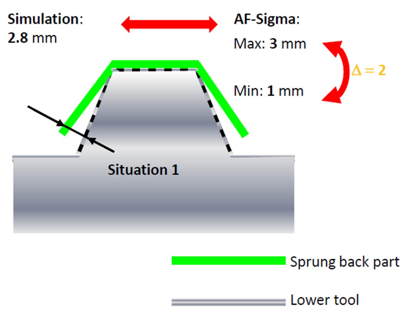
Figure 2: Springback deviation.
Finally, it was time for the compensation of the tools. Due to the particularities of this project, where the final part was laser cut, the compensation strategy was directly defined. Comparing the springback results after the laser cut with the nominal geometry of the part, the tools of the drawing operation were compensated. Several compensation loops were needed until the dimensional target was reached.
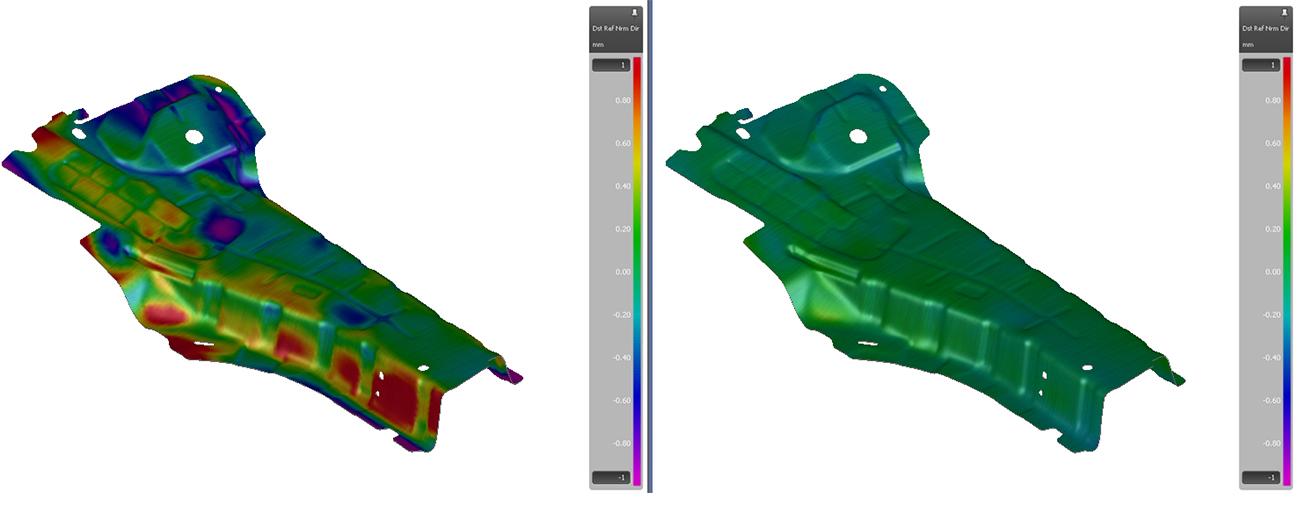
Figure 3: Left, not compensated part out of tolerance. Right, compensated part inside tolerance.
Already with simulation results according to the necessary quality, it was time for the machining of the tools, the subsequent assembly of them and finally with the tryout work in the tool shop. For this phase, ArcelorMittal shipped Fortiform®1050+EG and Fortiform®980+GI prototype blanks to Grupo Segura so the prototypes could be created and tested. The results demonstrate that Fortiform®1050+EG as well Fortiform®980+GI offers good formability (Figure 4).
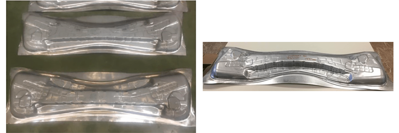
Figure 4: ArcelorMittal shipped Fortiform®1050+EG (on the left) and Fortiform®980+GI (on the right) prototype blanks to Grupo Segura for stamping trials assessment [Copyright Grupo Segura]
Under the advice of ArcelorMittal and together with Grupo Segura, they compared simulation results with the real part after the drawing operation, and a high degree of correlation was found in terms of formability, springback, thinning and material drawn.
Reality Matching Simulation
After this analysis, and thanks to the collaboration of Grupo Segura, ArcelorMittal and AutoForm, the viability of forming Fortiform (AHSS 3rd Generation) has been demonstrated. As well as the vital importance of characterizing the material to use it in AutoForm and obtain results adjusted to reality, anticipating the behavior that the part will have before starting the manufacturing process and of course having a team of professionals with wide experience in the sector, to reproduce all the simulated results in the real process.


?")


