
New Compensation Workflow Optimizes Process Planning to Tool Creation
Mitsubishi Motors Corporation (hereafter called MMC) executed an evaluation of four different software packages that support surface compensation with a focus on reducing the man-hours required for the compensation of surfaces while improving the balance between surface quality and accuracy. In this post, they share their test of AutoForm.
The problems with the previous method of compensation creation
MMC had been using software to create compensation surfaces for the panels. However, some issues were always present, regarding surface quality, appearance quality, man-hours, and workflow.
Surface quality issues
With the surface creation software previously in use, twisting, waving and tangential problems were often found on the compensated surface, requiring correction by hand.
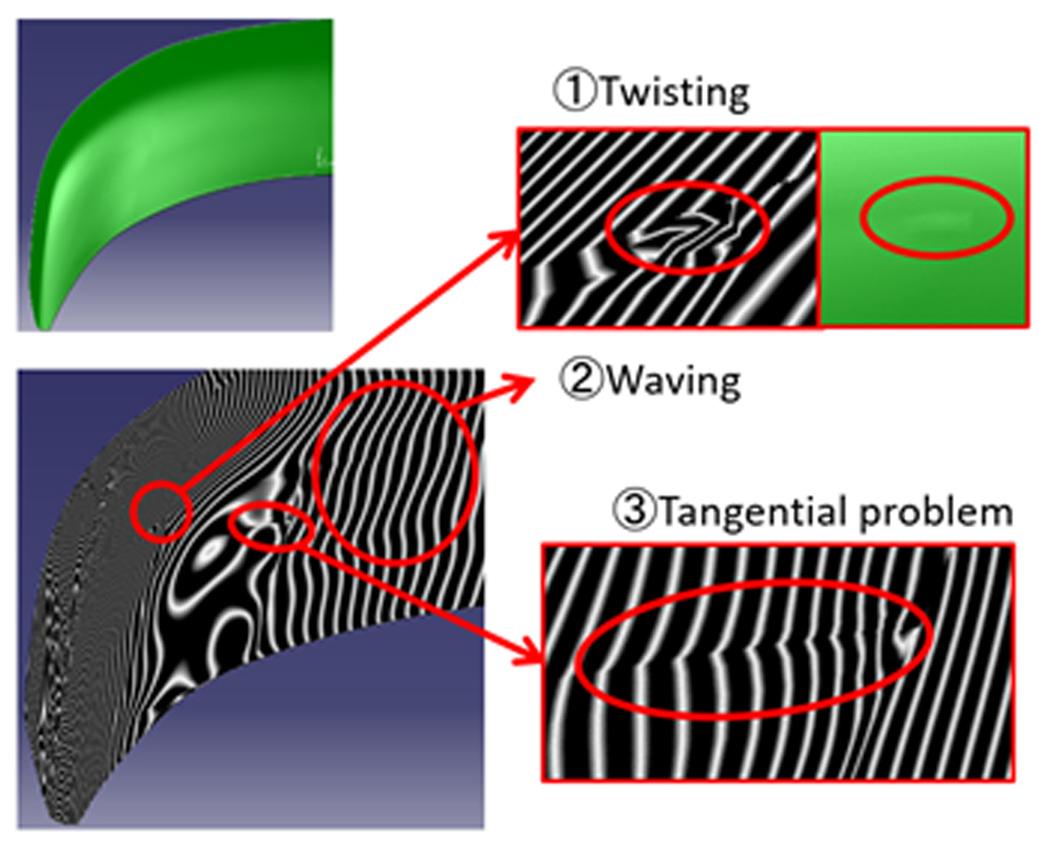
Fig. 1: The issues found on the compensated surface
Appearance quality issues
On the compensation surface created based on the CAE springback simulation, the curvature was partially reversed with respect to the part geometry (Figure 2). This reversed curvature was inevitably transferred to the panel causing it to fail the visual inspection even if it satisfied the required surface accuracy. The tool had to be reworked, incurring the significant amount of time for the surface correction.
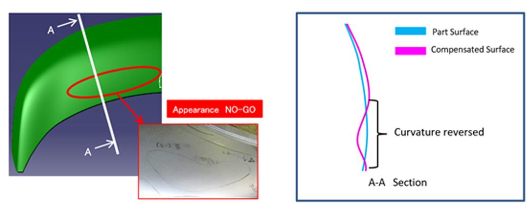
Fig.2: Reversed curvature
Workload issues
In order to satisfy both the surface quality and the compensation requirement, the surface had to be refined manually by hand after using the previous software. Laborious and dependent on tryout skill, this incurred a large amount of workload.
Mr. Shunsui Haraguchi, at the Production Engineering Division stated:
“If you prioritize the accuracy and tighten the compensation requirements, the surface quality will deteriorate, and the formed panel surface will have irregular bumps or folding lines. On the other hand, if you prioritize the surface quality, you will not satisfy the compensation requirements, and the compensation will not work as intended. As the compensation requirements and the surface quality forms the trade-off relationship, it is difficult to find the optimal balance between them.”
Workflow Limitations
With the conventional workflow (top of Figure 8), a fully compensated surface was created, followed by springback simulations. This task was repeated several times until the compensation requirements were satisfied. Then the drawing process was released to the CAM group for creating ready-for-milling surfaces. The high quality surface is indispensable for milling, however, improving the surface quality can be very difficult if the compensation requirements must be kept intact. Thus, a huge amount of workload is spent on the surface correction, and only a limited number of surfaces could be handled within the timeframe for the NC data preparation.
Problem Countermeasures: Four Software Types Evaluated
To work on these issues, MMC set out to select a new surface creation software to replace the conventional one. The software selected for the evaluation were (1) the conventional surface creation software, (2) a popular simulation software in use in Japan, (3) a fully compensated surface creation software not used in the company, and (4) AutoForm-
ProcessDesignerforCATIA. The evaluation was conducted from 2017 to 2019. In 2020, the final evaluation was conducted to verify surfaces of the actual outer panels, which was NC-milled in the machine used for real production.
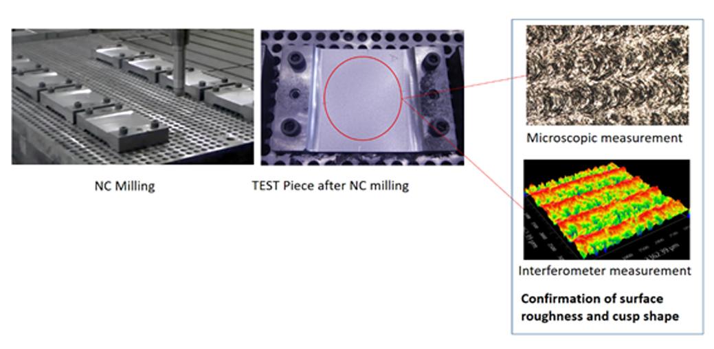
Fig. 5: Evaluation with a test piece
In their software comparisons, MMC assessed the following factors: 1) curvature continuity, 2) deviations from the compensation requirements, 3) waviness, 4) missing surface, 5) operating time, 6) usability of surface quality adjustment, and 7) link to CAE software.
“The decisive factor is the link between AutoForm-ProcessDesignerforCATIA and AutoForm-Compensator. With AutoForm-ProcessDesignerforCATIA, we can create a compensation surface using the compensation data transferred directly from AutoForm-Compensator. In this way, we can reduce the workload significantly” (Mr. Hayashi). With this, MMC decided to implement AutoForm.
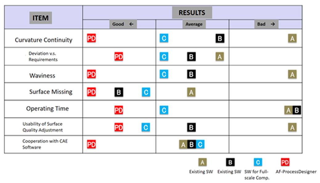
Fig. 6: Evaluation of the fully compensated surface creation software
The actual workflow is as follows. First, the process engineers create the base surface, run the springback simulations, and use AutoForm-Compensator to work on the surface compensation. Then, they call in the upstream Process Planning team and downstream CAM team to review the compensation strategy together. If the surface compensation does not match the compensation requirements, the procedure is repeated, usually 2~3 times, until the surface satisfies the requirements. Once approved, the CAM engineers create the compensation surface with AutoForm-ProcessDesignerforCATIA. After that, the process engineers run the final validation simulations, and release the process drawing to the CAM team, who creates the ready-for-milling surface and works on the NC data preparation. It is then transferred to the Fixture and Tool sector for the NC milling, and the actual tool is manufactured (Figure 8).
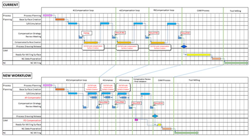
Fig. 8: Change in the workflow at the startup of the tooling stage
(Click to enlarge)
“The workload for the CAM team to create a milling surface is shrunk to 1/10. In the past, we could only create fully compensated surfaces only for a few parts like 1 or 2 hood outer panels per a car model. Now, with the new workflow, we can create the surfaces for 6 processes with 5 parts, and we are planning to double them to 19 processes with 5 parts in the coming new car models. Once we get used to the new workflow and obtain know-how, we should be able to deal with even larger number of parts” (Mr. Haraguchi).
“By reducing the workload for the fully compensated surface creation while improving the surface accuracy, the overall tooling process is now optimized. If the accuracy is poor in the early stage, it takes significant time to improve the accuracy later in the tooling try-out stage, which obviously increases the workload. Even if the analysis takes long in the early stage, the accurate analysis will shorten the quality-improvement loops in the later try-out stages, leading to the overall optimization. Although we have done a lot more than simply introducing AutoForm-ProcessDesignerforCATIA, the accuracy is much better now than in the past and the overall engineering quality has also improved” (Mr. Hayashi).
This is not just the opinion and experience of a single customer. You can read other similar cases on the WWW.Formingworld.com/Blog/. For example “SDM Korea Sees 100% Increased Work Speed with Compensation Modeling!” tells as similar story about surface quality and speed of implementation of the desired compensation amount.
(From left) Mitsubishi Motors Corporation – Mr. Suzuki (Process Planning), Mr. Haraguchi (CAM), Mr. Hayashi (Manager), Mr. Tanaka (New Technologies CAE)
Company Overview
Mitsubishi Motors Corporation
Established: April 22, 1970
Location: 3-1-21 Shibaura, Minato-ku, Tokyo
Representative: Takao Kato, Director, Representative Executive Officer, President & CEO
Capital: 284,382,000,000 yen
Net Sales: 1,455,476,000,000 yen (consolidated: as of the end of March 2021)
Number of Employees: 30,091 (consolidated: as of the end of March 2021)
Business Description: Development, manufacture, and sales of cars and car parts, financial business
URL:https://www.mitsubishi-motors.co.jp/


?")


