
1. Goals and Needs
The unique characteristics of aluminum sheet materials make it challenging for tryout personnel to optimize the final physical adjustments after manufacturing the die for an aluminum panel. Additionally, maintaining control over the quality loop is difficult. Therefore, it is crucial to assess and mitigate the risk of appearance defects during the process and die design stages for aluminum panels.
1.1 Aluminum Sheet Material Characteristics for Forming
Aluminum sheets have a lower density than steel sheets and are prone to sticking and galling to the die during stamping. The low Young’s modulus of aluminum results in significant springback after forming. Combined with low elongation and forming limit curve (FLC), these characteristics increase the likelihood of wrinkling and splitting. Furthermore, aluminum sheets are characterized by low hardness and susceptibility to age hardening, adding to the challenges of the stamping process.
1.2 Overall Improvement of the Die Process for Aluminum
To address the challenges outlined, four key steps are recommended:
- Part Optimization: Initiate simultaneous engineering early in the process to optimize part design. This includes adjusting shape for increased rigidity, adding fillets, and minimizing formability risks.
- Process Optimization: Simulate the stamping process using standards specific to aluminum sheets. Evaluate forming results for safety margin and verify the process layout, part positioning, cutting, and flanging/forming methods.
- Structural Optimization: Introduce design features such as ejection air holes and stripping structures, reduce pressing range and force, and refine trimming layout details.
- Manufacturing Optimization: Ensure sufficient forming margins to accommodate material fluctuations. This includes attention to roughness, die-spotting level, draw-in control, cutting angle, and flanging clearance.
2. Formability Defect Prediction and Prevention
Formability defects in aluminum panel production include wrinkling, cracking, and skid lines, as illustrated in Figure 1. Cracking occurs when material strain exceeds its limit, while wrinkling results from localized material accumulation. Skid lines are caused by the impact of the die or punch on the sheet metal, leaving contour imprints on the surface of stamped parts.
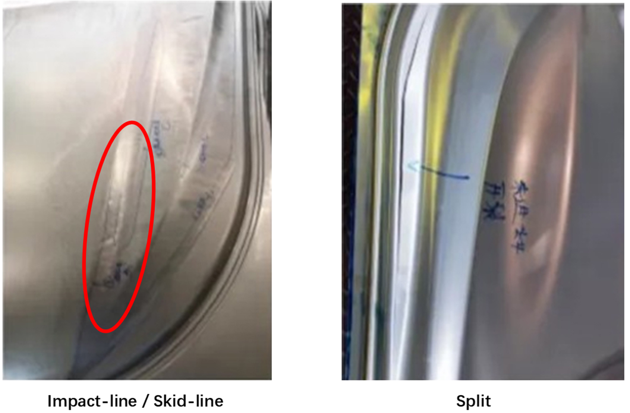
Figure 1: Examples of formability defects
3. Appearance Quality Defect Prediction and Prevention
Appearance quality defects arise in highly visible “A-class” areas, primarily consisting of distorted zebra line reflections and unclear or poorly defined feature lines, as shown in Figure 5.
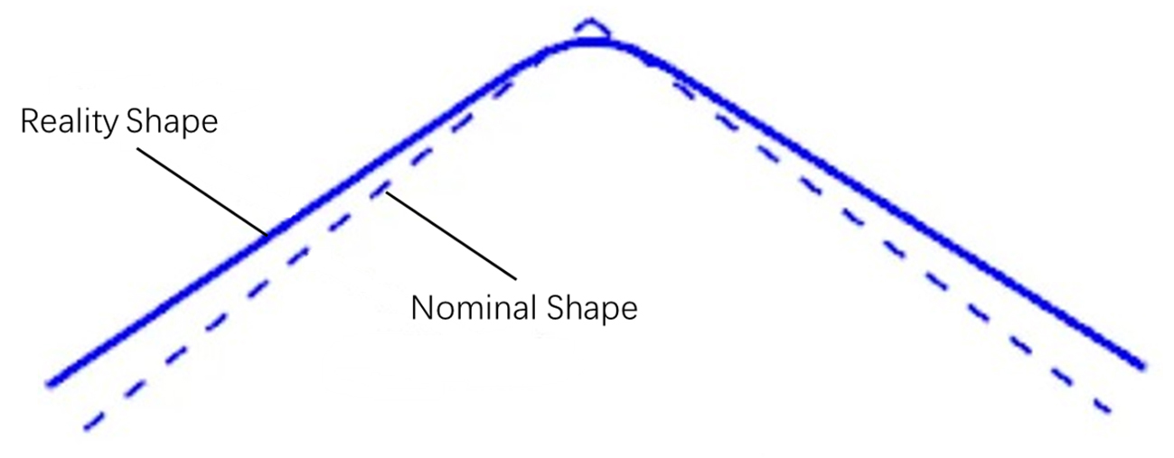
Figure 5: Unclear feature lines
3.1 Prediction of Appearance Quality Defects
Appearance defects can be predicted by comparing the zebra patterns of nominal data, CNC surface data, and final stamped parts. Differences in these patterns indicate the final panel has rebounded. Feature line clarity is assessed by measuring the angle and length. Angles exceeding 154°, arc lengths under 6 mm, or radii smaller than 48 mm are indicators of unclear feature lines.
3.2 Preventing Appearance Quality Defects
Appearance defects can be mitigated by adjusting the compensation factor to reduce springback values and optimize the compensation area. By aligning the zebra pattern and line length of the compensated data with the nominal part, defects can be minimized. Additionally, refining the “A-class” surface based on springback compensation data helps smooth zebra lines, as shown in Figure 6.
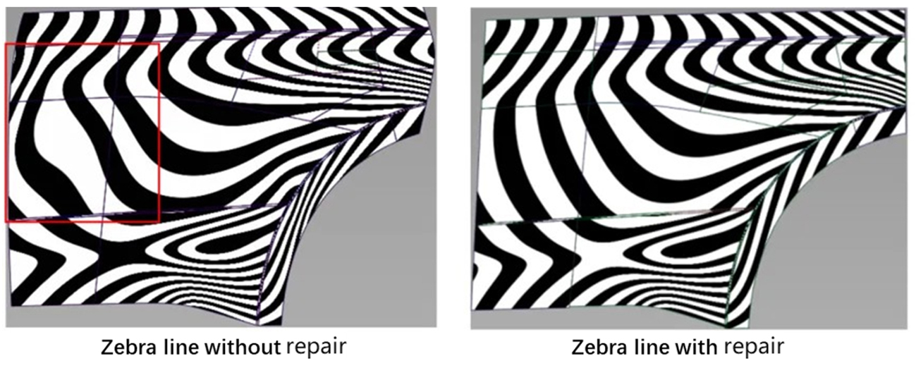
Figure 6: Comparison of repaired compensation results
If feature line clarity does not meet the prediction standard, countermeasure designs for the die structure should be implemented, as illustrated in Figure 7.
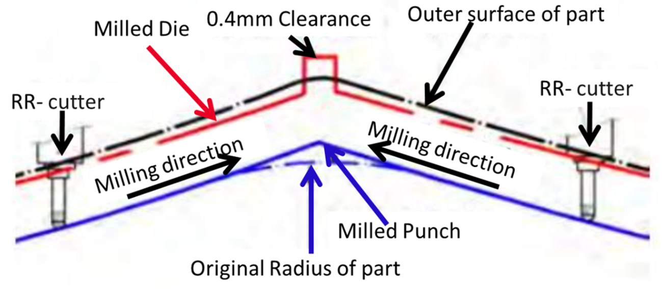
Figure 7: Feature line design adjustments
4. Surface Quality Defect Prediction and Prevention
Surface quality defects refer to areas on the part’s surface that lack smoothness, including surface lows, fillet irregularities, and indentations, as shown in Figure 8. Zebra line analysis, as discussed in the previous section, is a key tool in evaluating these defects.

Figure 8: Examples of surface quality defects
4.1 Prediction of Surface Quality Defects
Surface quality defects can be predicted through a comprehensive evaluation of CAE analysis, part shape, tool shape, process layout, and manufacturing experience. Figure 9 demonstrates the evaluation of surface lows in a CAE environment. Insights from prior projects serve as a reliable reference to assess the severity of surface lows and other defects.
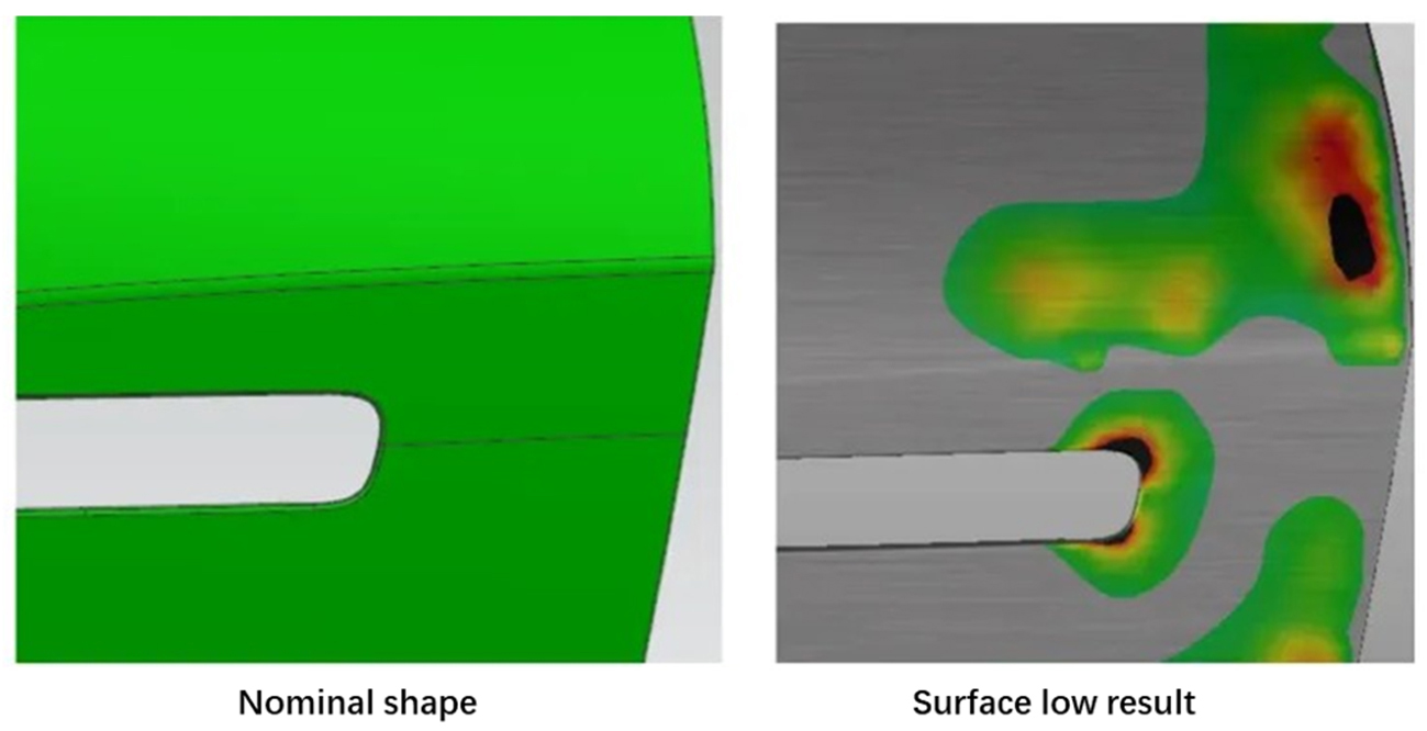
Figure 9: Prediction of surface quality defects through simulation
4.2 Prevention of Surface Quality Defects
- Process design stage:
- For surface low issues, modify the addendum and optimize the drawbead to control the draw-in for sufficient formability.
- For fillet irregularities in flanging, increase the transition area and adjust the timing; for re-strike, reduce the forming amount.
- To prevent indentations, avoid using scrap-cutting tools and refrain from placing multiple tools in the same area to minimize chips.
- Structural design stage:
- Position N2 gas springs on the pad close to the defect area.
- Ensure that all cutting tools simultaneously engage with the sheet.
- Prevent unworked areas from contacting the sheet.
- CNC data design stage:
- Apply strong pressure for all defect-prone areas and reduce gap values in high-risk areas.
5. Application Examples
The aluminum hood outer is a common component in Body-in-White (BIW) applications and represents a well-documented example of process improvement.
5.1 Basic Information of the Die
The hood outer is made from 6016-T4 aluminum with a thickness of 0.9 mm. The upper surface serves as the reference side, as shown in Figure 10. The stamping process consists of four operations: OP10 Draw, OP20 Trim and Piercing, OP30 Trim, and OP40 Flange and Trim, as shown in Figure 11.
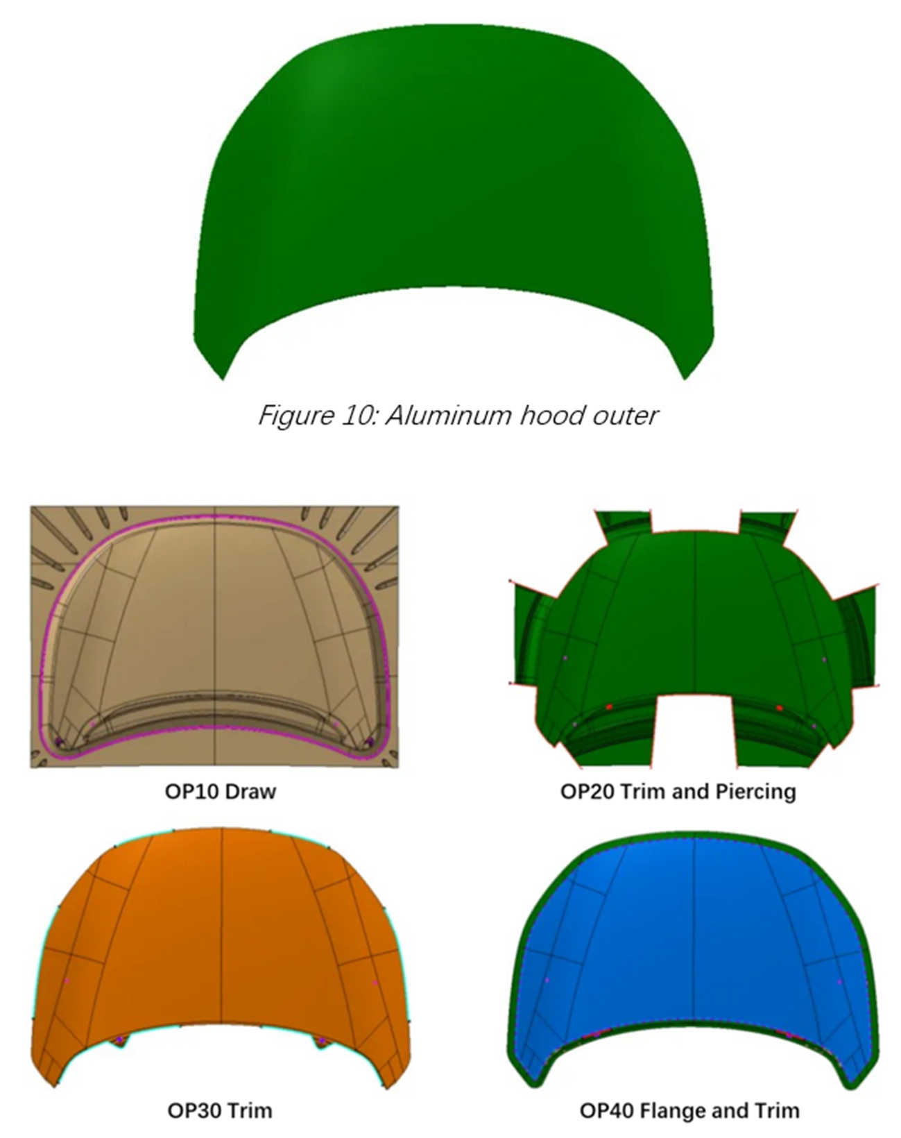
Figure 11: Stamping process layout
5.2 Improvements in the Design Stage
1. Process design stage,
a. Adjust the drawing depth and material take-up groove on the windshield side to enhance stretching without causing wrinkles or cracking, as shown in Figure 12.
b. Conduct a springback analysis of the entire process, apply compensation, and compare the zebra line on the compensated surface with the nominal, as shown in Figure 13.
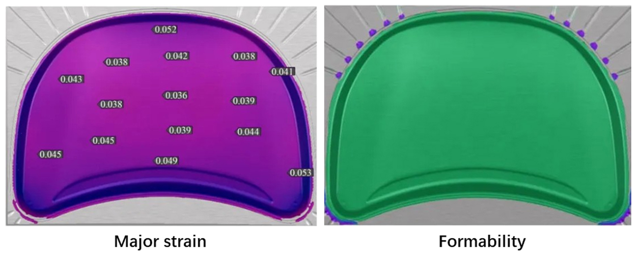
Figure 12: CAE result (draw operation)
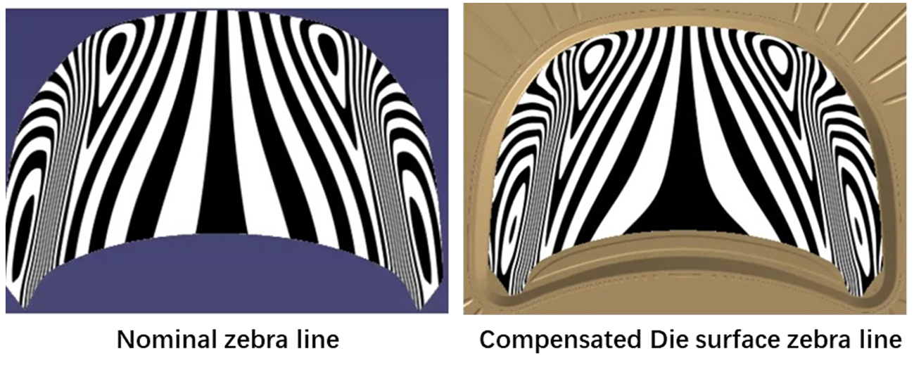
Figure 13: Zebra line comparison
2. Structural design stage:
a. Ensure the upper cutting tool engages the sheet simultaneously, with a cutting amount of 3 mm.
b. Reserve necessary working surfaces and reduce processing volumes for the remaining areas through casting (pad).
c. For the flat hood outer panel, retain more working surfaces in the lower die structure (post) for support and positioning, as shown in Figure 14. After CNC, machine excess surfaces based on actual production requirements.
In the structure design and CNC data design stages, based on the above specifications, the cutting tool and contact surface are specially designed, as shown in Figures 14 and 15.
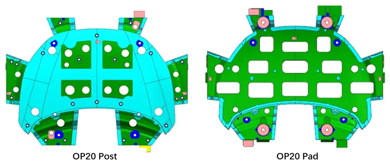
Figure 14: Die structure
3. CNC design stage:
a. Design the pad’s working face with strong pressure throughout the process, setting different strong pressure widths for different operations (e.g., 15 mm for cutting and 40 mm for flanging).
b. Avoid non-working surfaces to prevent empty spaces, maintaining a 1 mm clearance from the product surface and a 2 mm clearance from the addendum surface.
c. Ensure smooth transitions for strong pressure and avoidance on A-Class surfaces, as shown in Figure 15.
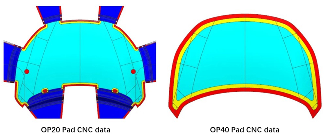
Figure 15: Die CNC data
5.3 Manufacturing Guarantee and Effect Verification
The forming effect was validated on the press machine. The initial pressure blue oil coloring rate of the hood outer exceeded 75%, with no cracking or wrinkling issues. The zebra pattern on the part was consistent with the data, and no A-class defects were observed, achieving the goal of an exceptional process, as shown in Figure 16.
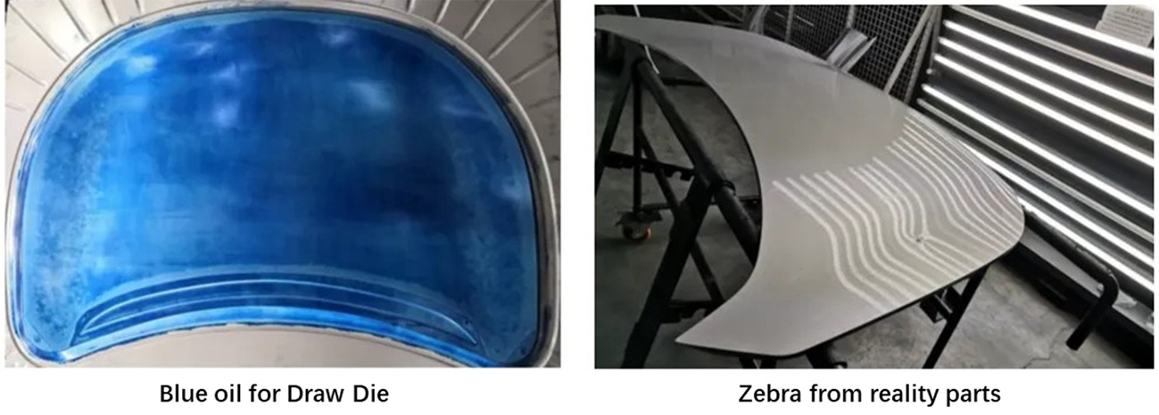
Figure 16: Final aluminum hood outer


?")


