
In this blog post we will have a closer look to coining which takes place in stamping operations and the usage of new thick shell elements in AutoForm will be demonstrated. We also share the results of a Bilstein-AutoForm joint project, where the effect of coining in deep drawn cups was investigated. The results of this project were presented during Numisheet 2018 in Tokyo and the corresponding full paper can be found here (open access).
What do we mean by coining?
The coining that we encounter in stamping operations involves forming of sheet material between two tools having a clearance less than the current thickness of the sheet. In other terms, the sheet is compressed in thickness direction between two rigid tools. “Re-strike” or “calibration” are some other terms to describe this deformation. But why do we do that?
Why coining?
The main reason for performing coining is to reduce springback and increase dimensional accuracy of the part. Especially by coining the bent regions of the part the bending effect in those regions is minimized and more homogeneous compression is superimposed. In order to demonstrate this effect we can consider the following use case where a part in transfer press is formed with double symmetry. Click play:
Video 1: How the part is manufactured
The processes in the video were: drawing, trim, flanging the back part (F-50 below) and flanging the front (F-60 below), finishing in final trim. The material is HCT600T with 1.0 mm thickness.
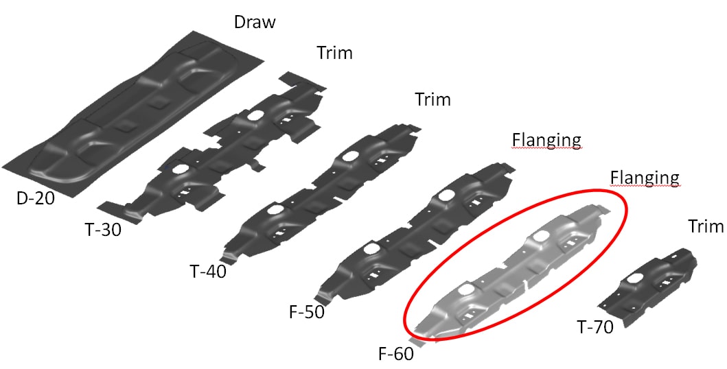
Fig 1. From flat sheet to case part
When we just consider the flanging process in F-60 we see that we get springback values beyond acceptable limits as shown in the following video.
Video 2: The flanging operation leads to springback beyond acceptable limits.
In this particular example the spring back values are almost 3mm. Most customers however have their own limits and work within tolerances of +/- 0.5mm. In dealing with compensation it is not possible to over-bend the flanged area, seeing that this would result problems, as it will now be back-drafted. What most process engineers do is stop at this stage. They know from experience, gained from previous projects, that their ‘tool shop solution’ works.
The tool shop will now attempt to solve such issues manually by adding a coining operation which compresses the radius, being the specific upper radius where the metal is bent to form the flange. The flanging steel is designed in such a way that it also covers the part radius. The height of the steel is arranged by “shimming”, being a thin plate placed against the part. This is done completely by trial and error as they experiment by adding additional height to the tools.
Why just trial and error?
The reason lies in the formulation of the shell elements which are the “standard elements” for sheet metal forming simulations. With these elements it is not possible to simulate coining or ironing where the clearance between the tools is smaller than the current sheet thickness. In other words, conventional shell element is “blind” to the gaps smaller than sheet thickness. This is known by the process engineers and therefore they always work with a tool offset of nominal sheet thickness. For that reason, the colleagues in tool shop do not receive any information regarding the amount of coining or “shimming.”
Solution
Our aim was to “give the process engineers the capability to model coining in stamping processes without additional effort and computation time.” For that purpose new thick shell elements were developed which will enable you to simulate coining and ironing inside AutoForm starting with its new release.
The effectiveness of the new formulation was verified with the help of a collaboration with the company BILSTEIN GmbH & Co. KG. In this project, coining was performed on axisymmetric cups with two different tools shown in the following figure. With the conical tool, the radius of the cups was coined and with the flat tool the bottom of the cups was coined.
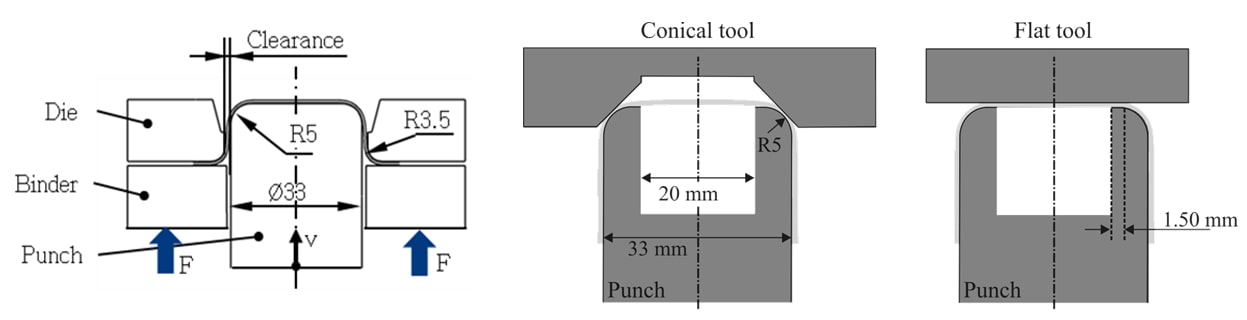
Fig 2. Left: Two stage forming process. Right: Coining with two variations.
The results showed that, in the use of both flat and conical tools, the simulated springback values are in good agreement with the springback from different section heights of the experiment (measured optically). It was also seen that thickness of the coined areas could also accurately be predicted under the defined coining force as shown below:
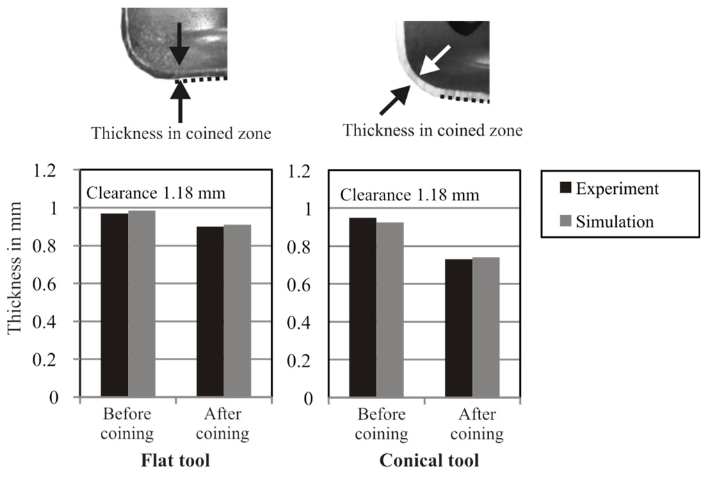
Fig 3. Thicknesses in coining zones before and after coining at a given force value.
Back to the process engineer
Now with AutoForm’s new thick shell element the user is able to simulate the coined area where the thickness shall be reduced (shown in the red area in the below video). The process engineer can decide on the level of coining and see the effect of coining on springback immediately. With the process engineer enabled to actually simulate and share this information, their tryout no longer needs to start out with zero information before coining. Following video shows the coining step in the aforementioned part and indicates whether or not the area is being coined or not.
Video 3. Coining under transfer press.
In this use case, the additional coining decreases the springback significantly which is captured by the thick shell elements (figure below).
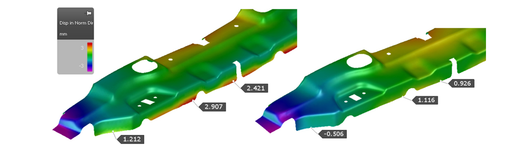
Fig 4. Reduced springback captured by thick shell element formulation. Left: without coining Right: with coining
Lastly, the work piece demonstrated that the use of the enhanced thick shell element only required an additional 8% simulation time as compared to the conventional version. That’s some time that will save hours, maybe even days, spent in tryout.
Thank you Alper for this great post!
New readers; if you subscribe to our blog you’ll get just one email per month pointing you to our top rated posts for that month. We’ll never send you any marketing emails, just pure metal forming news!


?")


