
The Workshop of Japanese Society for Die and Mold Technology has been taken placed in Fukui, Japan on Nov 29, 2018. An introduction about the New Smart Die Design Processes and Springback Compensation Technologies by utilizing AutoForm Solutions has been presented by Brian Su, AutoForm Japan, during the morning session of the workshop.
As one of the cores of the “Smart Die Design Processes and Springback Compensation Technologies”, we believe that, “CONTROLING” the behavior of the Springback before compensation does play an important role in order to ensure dimensional integrity and successful springback compensations, In the other word, at first, it is recommended to modify the processes to reduce the amount of springback as much as possible, and then make sure the processes is robust and stable enough by using AutoForm before starting a compensation process (Fig-1). Especially in the use cases of outer panels, it is crucial not only to satisfy the milling criteria, but also required to prepare high quality surfaces by taking into consideration the surface defect countermeasures and the tool deformation which are very complicated and delicate processes.
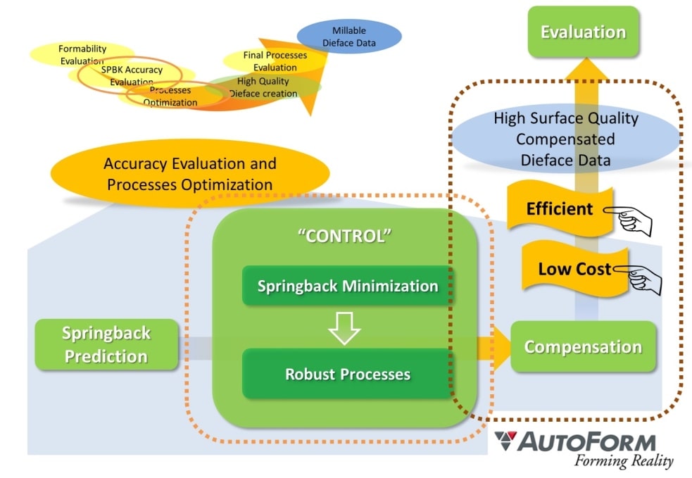
(Fig-1) Precondition of a successful springback compensation
The framework of this “Smart Die Design Processes and Springback Compensation Technologies” is basically divided into three stages as shown in (Fig-2). In the 1st stage, starting from the 3D part geometry, AutoForm supports our customers to quickly generate parametric die face design which the formability can be easily analyzed and evaluated in order to meet with the process planning, production quality, time and cost specifications. Continuously the information of parametric die face design is transferred into CAD system via AutoForm-Quicklink.
In AutoForm-ProcessDesignerforCATIA , nominal geometries with high surface quality and processes can be quickly generated and managed. At the 2nd stage, we validate the processes by using high surface quality CAD data, and then study the springback compensation strategies to minimize the springback in AutoForm, and then utilize the vector field generated from the evaluation results to perform springback compensation and create millable compensated surfaces. At the 3rd stage, we will perform final validations to ensure the compensated CAD quality surfaces and processes satisfy all requirements. In this comprehensive workflow, data exchange between CAE analysis and CAD systems are also systemized through the parametric transferring interfaces so that the workflow and data flow are integrated into one PLM/PDM system which the consistency of necessary information thru the entire workflow can be parametrically maintained and managed.
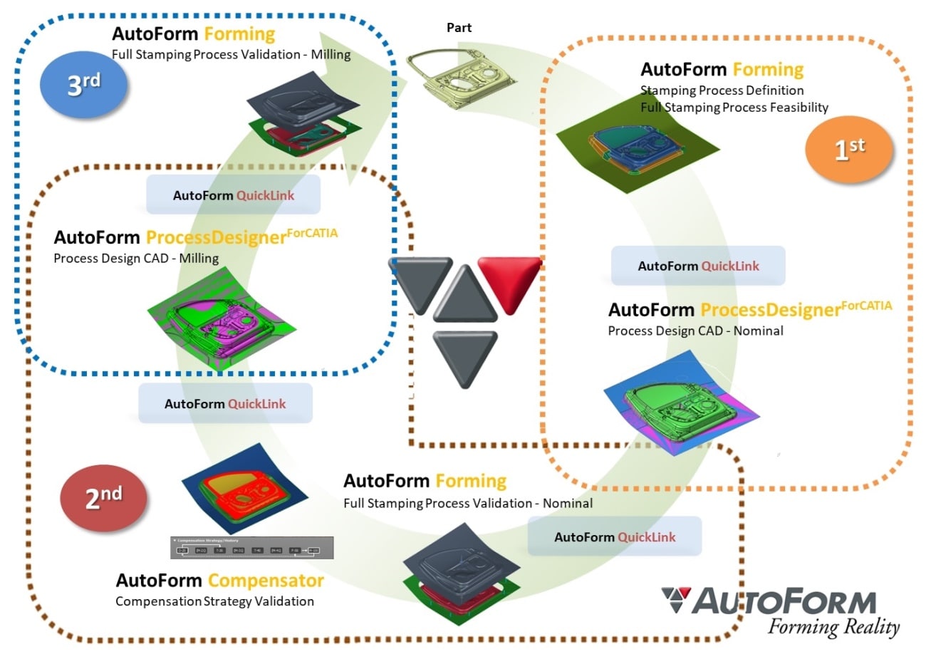
(Fig.2) Smart Die Design and Springback Compensation Processes
In this article, we would like to focus on the 2nd stage, that is, an easy-to-use system of springback compensation by utilizing the vector fields carried out from the evaluation results of AutoForm.
Experience in Japan is advancing, with an increasing amount of Japanese customers utilizing AutoForm for compensation. One of the developments has been to help engineers grow beyond the time-consuming practice of exporting compensated surfaces (in an IGES format and reworked in CAD), which itself leads to inconsistency in maintaining data across different systems. Instead, AutoForm proposes a new concept for an efficient springback compensation as below.
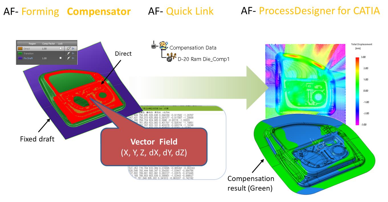
(Fig.3) Compensation by utilizing vector field
As shown in (Fig-3) above, the vector field via a text format with coordinate info and vectors is generated from AutoForm. In AutoForm-ProcessDesignerforCATIA, users only need to define compensation regions with different types of compensation methods, and then simply perform the spring back compensation, i.e. compensate the original surface, which is a very easy-to-use process.
As shown in (Fig-4), there are three major types of options to compensate the surfaces: (1) Vector Field Compensation which users can utilize vector field directly; (2) ReferenceToTarget Compensation where users can define reference and target surfaces by using very high quality of Bezier surfaces. Thereby, vectors are automatically calculated and applied to the defined compensation region within the system. A use case of this option is for instance to generate a very smooth binder area of a door inner; (3) Transformation which users can easily fix or transform some specific regions such as mating surfaces. Finally, the system automatically combines all the types of compensation areas, thereby generating a very high quality of compensated Die face within a very short time.
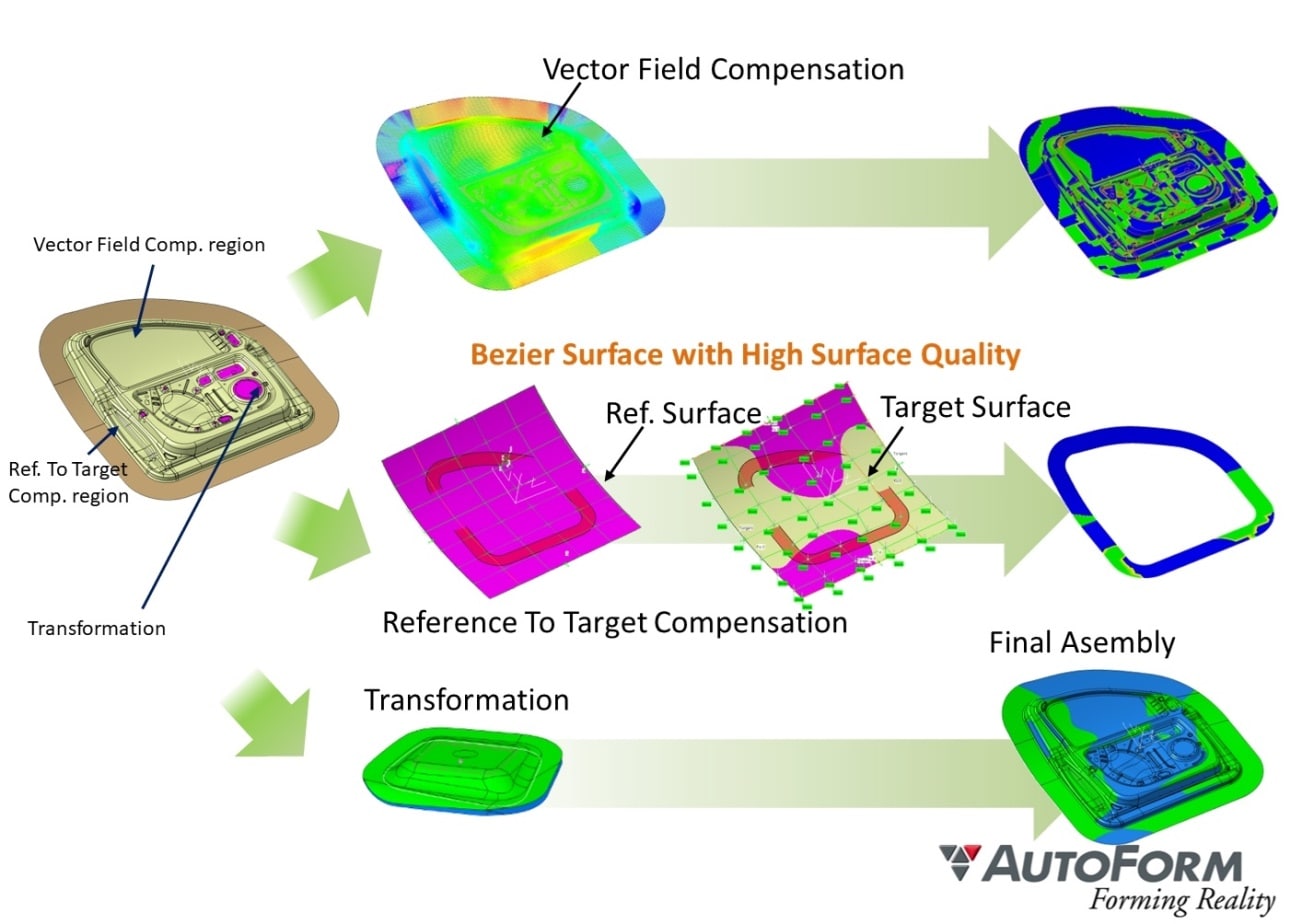
(Fig-4) Various types of Compensation AutoForm-ProcessDesignerforCATIA
After performing the compensation, there are several types of embedded analysis features which can help users analyze the compensation results such as displacement analysis, deviation analysis, volume analysis, and curvature analysis…etc.
One of the Japanese car manufacturers has verified the capability of Compensation within AutoForm-ProcessDesignerforCATIA to satisfy the milling quality criteria of class-A surfaces through an outer panel project. Furthermore, significant time-saving is also expectable by utilizing this new workflow and technology. In the future, we plan to work on more and more projects with Japanese customers to continuously accumulate know-hows by utilizing this New Smart Die Design Processes and Springback Compensation Technologies for practical applications in Japanese market.


?")


