
The design and manufacture of hot-formed parts and the development of their manufacturing processes is more complex than cold stamping processes, demanding greater specialist expertise and experience. Hot stamping also requires more advanced resources to identify potential difficulties and obtain parts that meet all defined requirements.
In addition to the care invested in designing the hot-formed parts themselves, the stamping and quenching processes must be very carefully defined to form the part properly despite the draw-in limitations. This is because the blanks are generally pre-cut, which prevents the extensive use of standard blankholders and drawbeads employed in cold forming. In addition, the martensitic transformation must be completed within the time specified for the process to avoid excessively long manufacturing cycles that in turn increase the final product cost. Special care must therefore be taken when designing the inner holders and movable inserts that prevent the sheet from wrinkling, as well as the tool cooling channels to ensure fast cooling during production.
The following factors must be taken into consideration:
- The part geometry must be simplified so the parts can be produced in a single forming step.
- Vertical walls should be avoided so that the press force can be converted into sufficient contact pressure between the tools and the sheet to ensure the requisite quick thermal exchange during the quenching phase.
- Post-quenching cutting operations need to minimized, which nearly always requires the use of pre-cut blanks and a minimal number of holes. To permit this, the tolerances of the part edges, both in the contour and in the holes, must be adjusted (widened).
- It is sometimes necessary to define areas of the part where martensite should not be formed to ensure higher ductility or local weldability. In these cases, welded blanks with sections of different materials (tailored blanks) or local heating/cooling can be used.
- The parts are often reinforced locally with overlapping sheets (patchwork), which are welded onto the original blank to ensure maximum strength with minimum weight increase.
Applications for different goals and stages
Engineering best practices involve the use of digital simulation in two phases: process feasibility analysis of the part with essential parameters and final process validation considering all relevant details of the actual production state.
First stage with essential engineering parameters
First, it is necessary to design the part to achieve feasible production using this technology. For this purpose, process simulation is used to identify and solve potential problems through changes in the geometry, of both the product and the tools. That’s in addition to determining the most appropriate parameter adjustment of the process itself. In this first phase, the simulation model used can be prioritized with the most important parameters such as geometry, tool kinematics, material standard, pressure and process. Consequently, the engineering team can deal with these parameters first and gain agility to save engineering & computing time. This allows for the implementation of a greater number of tests to develop the best process, as each project may require several simulations.
The aim of this phase is to detect critical stamping problems such as wrinkles, splits, dimensional deviations, and so on, which must then be corrected. Figures 1, 2 and 3 show some of the problems that can be addressed at this stage:
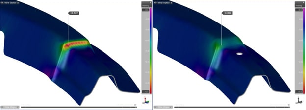
Fig. 1: Excessive thinning corrected by changing the geometry of the product.
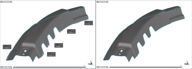
Fig. 2: Dimensional deviations corrected through blank contour adjustment with trim line optimization.

Fig. 3: Wrinkling of the sheet corrected by changing the inner holder.
Second stage with detailed engineering parameters
After defining the details of the part and the process in the first stage, it is now time to develop the detailed tool design, with special attention to the quenching process. At this point, the tool design is inching closer to reality, transforming into actual and specific quenching entities in production engineering. Here, the rapid and homogeneous cooling of the sheet must be guaranteed in order to achieve complete transformation of the microstructure austenite into martensite while the press is still closed. This not only makes it possible to obtain adequate strength in the part, but also avoids possible distortions due to the differential contraction of the other steel phases, such as pearlite and bainite, before final cooling. For this purpose, process parameters – such as contact pressure, quenching cycle duration, and optimum distribution of the tool’s cooling channels – must be defined very carefully.
In this phase, the simulations must therefore be meticulously carried out, using the calculation parameters that ensure the verified and validated accuracy of the solver with physical experimental tests. Further, the simulations must take into account all the details consistently evolved from the essential parameters used in the first step – coefficients of friction, forces applied by the press, coupled-cooling transformation, heating cycles, temperature distribution in the tools, and dimensions and positioning of the cooling channels. Naturally, this implies longer calculation times per simulation; however, since the tool concept was already defined in the previous step, the number of simulations required towards the end of the project will generally be much shorter. Therefore, the longer calculation time of the simulations in this last step is usually not an obstacle.
The desired results in this phase relate to the microstructure of the sheet after quenching. For this purpose, the distribution of cooling channels must be defined to ensure that this microstructure is martensitic in all desired sections of the part. To ensure the accuracy of this calculation, it is essential to consider the temperature distribution on the tool surfaces; this is one of the determining factors of the thermal exchange rate between the tool and the sheet, and thus the cooling rate of the sheet. Heating and cooling cycles should also be considered, especially between the initial activation of the line and the point where equilibrium is reached, when temperatures begin to vary stably. All of this demands the use of a solid finite element mesh for the tools in the simulation model, as opposed to the flat element mesh used in more simplified models, where the surface temperature is specified rather than calculated (the sheet mesh is always flat). Figure 4 shows examples of models with user-defined cooling channels, as well as the solid mesh used for representation and the temperature distribution obtained after calculation.

Fig. 4: Advanced simulation models of the hot forming process, including cooling channels and calculation of the tool temperature distribution.
This type of model is available in several simulation software solutions, with the most advanced software programs making its generation and the calculation of the coolant flow effects transparent to the user. Another example of the final result obtained by these more complete simulations is presented in Figure 5. It indicates the percentage of martensite obtained in each section of the part through successive forming and quenching cycles.
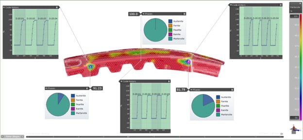
Fig. 5: Percentage of martensite in the microstructure of the final part after quenching, in successive forming cycles after the start of the line.
The results of these final analyses will confirm the usefulness of the tool concept defined in the project, including the distribution and diameter of the cooling channels. They also provide essential information for the detailed final tool design.
Conclusion
Hot forming processes are generally much more complex than traditional cold forming. This is due to the temperature influences and the different phases that the material goes through, the need to ensure rapid cooling in the quenching phase, and the limitations involved with cutting the material after quenching. Therefore, the use of simulation becomes even more essential to find optimum solutions regarding the manifold and sensitive engineering parameters governing the process.
Dividing the engineering workload into two successive and complementary phases allows for a practical and objective use of the available resources. Examining the basic parameters using feasibility studies serves to secure the process baseline. This must be coupled with additional parameter studies during final process validation as the process evolves and gets closer to the real production state.
Overall process accuracy can only be achieved by consistently associating and evolving the process along these two workflow phases. This enables the systematic optimization of hot stamping tools – addressing potential problems in the order in which they must be solved with minimum expenditure of time and resources.


?")


