
Transmuting Just A Few Millimeters of Material into Gold
In this article, AutoForm’s Gianfranco Ruggiero describes the challenges faced during the manufacture of trimming tools, particularly for transfer and progressive dies, and shows how simulation can save money, labor, and material while guaranteeing tool quality.
The typical trial-and-error approach used during tryout to determine the correct trimming tool blade position can be both tricky and expensive. Performing the same approach in the “virtual” world of CAE simulation is cheaper, faster, and delivers reliable final results. Aside from reducing down time, you can save plenty of man hours that otherwise would have been wasted in tryout.
First, we must consider a common stamping process, as represented below. In reality, the tools are not manufactured in the same order in which they operate in the production line.
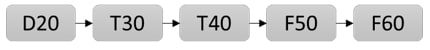
Figure 1 – Common Stamping Process Plan
The D20 drawing tool is usually built first, then the flanging tools, and finally the trimming tools. During the flanging tools trial though, the sheet exiting the drawing station must be trimmed, otherwise it would not fit onto the flanging tool. This operation is performed by laser machines.
Let’s therefore proceed in the working order.
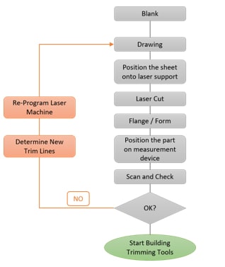
The workaround here is that after drawing the panel is laser cut, seeing the trimming tools are not yet ready. Then it’s formed or flanged to “get to” the final part. In this shortcut, the part is scanned with a measurement device to compare it with the required measurements. If we get a green light at this point, we can release the drawing die and start building the cutting tools according to the curve used by the laser. At this point, the trial is usually defined, completed and the tool released for buy-off.
I asked this question while visiting a tool shop recently: “ What happens if the outlines of the part rather than the edges or positions of holes are outside tolerance?”
To better explain this concept, let’s take a look at the example shown in Figure 3. The part is produced on a transfer die. We have two possible plans to evaluate:The response was, “Well, Gian, we face this issue often. We use the ‘as engineered’ trim lines to set the path of the laser but most of the time that does not work. When flanging, after trimming, holes may shift and outlines can easily be off. How far from being in tolerance are we? It really depends on how those curves were determined during process engineering. Here, we proceed with the typical trial-and-error approach. We measure the distance in all directions from the nominal part and we modify the trim lines accordingly. We enter the ‘new’ curve into the robot for laser cutting. We cut, flange, measure again and compare. Repeat again if it did not turn out right. Now consider when you form the flange in two operations.”
- Plan #1: the blank is larger than the part and we have to trim the curved area after the part is drawn in OP30, as shown in solution 1.
- Plan #2: the curved area outline is defined directly in the blanking operation before drawing, as shown in solution 2.
If we go with Plan #1, we have to add a cam to the trimming tool as the trim angle check (highlighted) cannot be trimmed with a vertical movement (ram). But if we choose Plan #2, we have to define the correct position of the trim line directly on the blanking station itself. This is to ensure that after the drawing operation, the outline will match the nominal geometry within tolerance.
Each option has cost factors. Plan #1 requires adding a cam and Plan #2, a blanking station. Value engineers can do the math. But if we consider the entire tool making process, which of course includes tool tryout, Plan #2 may turn out to be the more costly route. Making all of the final trimming tool adjustments directly during tool tryout can be time and money intensive. Eventually, it really depends on how “good” the engineering was in the first place and how the trim lines are determined.
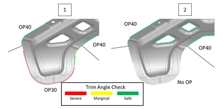
Figure 3 – Transfer Die Example: Trim CAM vs Crashform
Figure 4 below shows a result produced by Plan #2, without the trim curve optimization process. The highlighted area shows that the part is off from the nominal geometry by 2.6 mm.
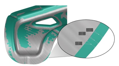
Figure 4 – Results vs Nominal – No Trim Line Optimization
If engineering leaves their tryout team to fix this issue and bring the part within tolerance, the number of workflow loops shown in Figure 2 could become costly. Think about how many people are involved in the process. Remember that by changing the blank size, the pressure distribution during drawing also changes, along with the strain of the sheet. This would generate a different springback behavior. Therefore, sometimes you would get a shorter and sometimes longer part.
In the case of progressive dies things become even more complicated. Smaller parts (usually, but not always) have several bending operations. These determine the correct trim line position during blanking on the flat sheet when the part will be bent more than once.
For example, let’s take a look at the part and the process shown in the figure below.
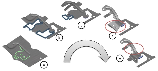
Figure 5 – Sequence of operations needed to produce the L-shaped flange of the support
Focusing only on the L-shaped flange, what happens when you have the green-lined shape in model “a” and you need to bend it into place to meet tolerances on the final forming operation?
The trim line optimization process implemented in AutoForm is a CAE solution based on the trial-and-error approach, during which the software adds or removes material until it reaches the target tolerance.
In other words, the software digitally replicates what tryout teams do on the real tool with the benefit of being a faster and cheaper process. Just as in reality, the simulation predicts and therefore considers the movement of the sheet in the drawing die and the positioning of the sheet on the trimming tool.
Below on the left, we can see the result obtained when applying the automatic optimization process for a part on a transfer die. You can see how the nominal and simulated sheet edges are now aligned.
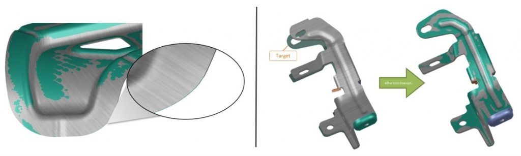
Fig. 6: Left: Results vs Nominal – Trim Line Optimization. Right: Optimization on a Part Produced with a Progressive Die.
The right side of Figure 6 shows a real part from FARA Stampi S.r.l., Italy.
From the comparison, we can see that the second simulation which included the automatic trim line optimization was greatly improved and ended up well within tolerance. FARA Stampi S.r.l. (part of the FARA Industriale Group) has since built the tool. In our discussion comparing simulation vs. reality, their CEO Mr. Elio Falco stated, “The trim line optimization feature has allowed us to effectively cut down tryout loops by 50%.”
Ultimately, digitally optimizing the trim lines benefits real-world tool manufacturing through the reduction of trial loops. Customers save time and money while ensuring target engineering quality and accuracy. With tolerances becoming increasingly stringent and with geometries ever more complex, where do you want to run your trial and error approach?
New readers, don’t forget to sign up to our blog. We’ll never send you any marketing emails. Just a regular update of the latest top post.


?")


