
FluidForming Case Study Demonstrates the Efficacy of Simulation on Complex Aerospace Part.
FluidForming Americas, LLC, headquartered in Tennessee, forms highly complex and repeatable parts for numerous quality- and precision-driven industries such as automotive, appliance, energy, and aerospace industries. Recently produced parts include fuel cells, battery enclosures, fan blades, and heat exchangers. The FluidForming hydroforming process employs the highest forming pressures in the metal forming industry – up to 60,000 psi.
To optimize part production and help customers achieve the highest levels of quality, accuracy, and repeatability, the company’s engineering team uses AutoForm to streamline production, optimize product design, control costs, and minimize material waste.
Although conventional, bladder-based hydroforming has been around since the 1950s, FluidForming is a bladder-free metal forming process that marks the first major innovation in metal forming since that time. This sustainable metal forming process uses highly pressurized water as the forming medium and allows for precise rapid prototyping and low- to medium-volume parts production.
Product Development and Optimization Process
FluidForming works with customers to improve product design to ensure successful production. The engineering team starts with a customer’s 3D CAD drawing and works collaboratively to learn more about what they hope to achieve with the part.
Then, the team runs the part through AutoForm’s simulation software to help further refine part design and optimize the part for the FluidForming metal forming process. This helps the development team identify and address potential issues before having a tool made or forming a single part … saving customers time and money.
Step 1: Value Engineering
→ 1-3 Weeks
Step 2: Tooling
→ 4-8 Weeks
Step 3: Set-up & Part Approvals
→ 2-3 Weeks
Step 4: Production
→ 1-3 Weeks
Every step of the FluidForming metal forming process — from material flow to clamping pressure to water volume and pressure — is variable and controlled. Forming pressures of up to 4,000 bar (60,000 psi) ensure that FluidForming achieves finer, more detailed results than any other metal forming process available to manufacturers today. And because the forming medium – water – comes into contact with just one side of the material, the process can also accommodate pre-finished or pre-painted metal surfaces.
Furthermore, the process requires just one tool, which dramatically reduces costs and production time. The FluidForming FormBalancer can accommodate 3D printed tooling as well as a variety of tool and mold materials including aluminum, hot rolled steel, and tool steels. The ability to use modular tooling and inserts allows for even more flexibility and offers a cost-efficient solution to forming complex parts.
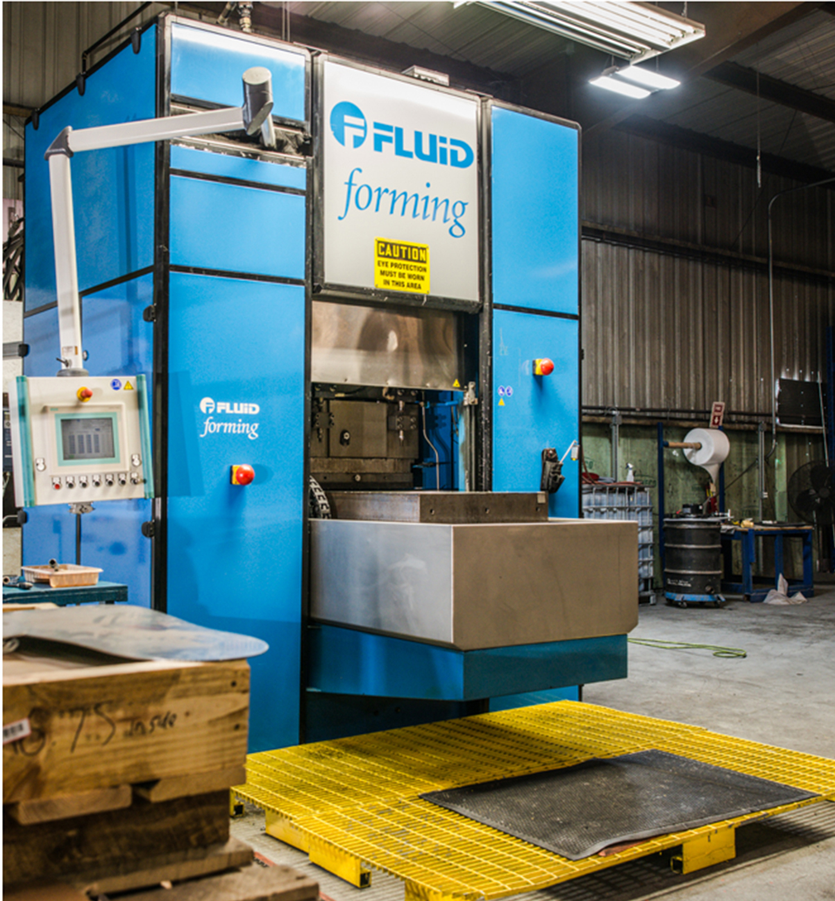
The FluidForming FormBalancer
Forming the “Impossible”
In collaboration with J&N Metal Product, headquartered in Brazil, Indiana, the FluidForming engineering team used AutoForm to optimize part design for an aerospace manufacturer.
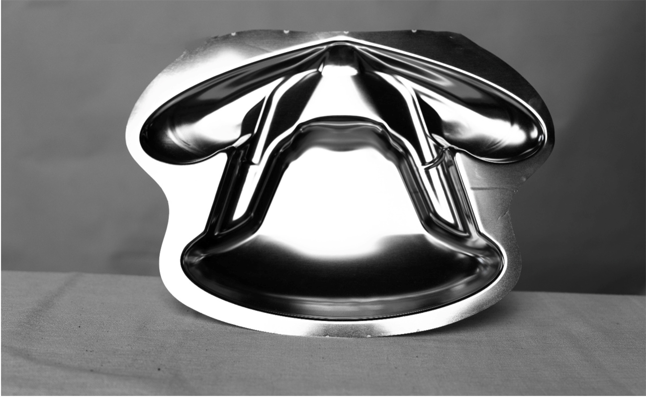
The image above is a prototype of a part produced for a well-known aerospace manufacturer. The buckle to the right is not part of the formed part and has no impact on the function of the component. Formed from Inconel 718, the part measures 18” x 13.5” x 2.15” (L x W x D).
“The ‘Butterfly’ part was nearing un-manufacturable until we found Fluid Forming Americas. Working with them on the material thickness and orientation resulted in a usable part on a very complex assembly,” said J&N project engineering lead, Austin Eckstein.
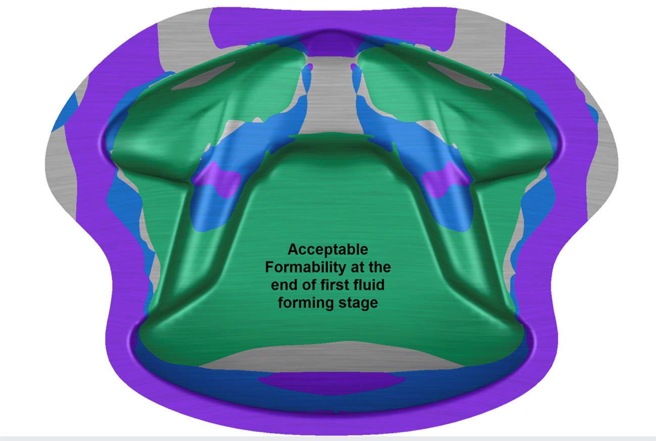
The simulation allowed the engineering team at FluidForming Americas to conduct an initial review of the part in terms of formability and material thickness. From there, the team was able to provide feedback to the customer regarding the process’s forming feasibility. It also enabled the team to recommend possible design changes that improved formability.
In this instance, the team discovered that the initial approach with a single forming step would lead to material ripping due to the sharp corner in the tool to achieve the desired “butterfly” part shape. To ensure a successful and repeatable outcome, a nested two-tool approach with intermediate annealing was employed. This innovative solution resulted in less material thinning in the critical areas and no ripping.
The forming pressures needed to form out the full geometry of the part was 120 kPa (17,500 psi) and 90 kPa (13,000 psi), respectively, for the first and second forming steps. Formed from Inconel 718, the material thickness was held above 0.030″ with a starting thickness of 0.039″ which equates to a total thinning of about 23% and was well within the desired range for the customer.
Below are images of the acceptable formability condition of the forming process at the end of the first and second forming stages, with an intermediate annealing step.
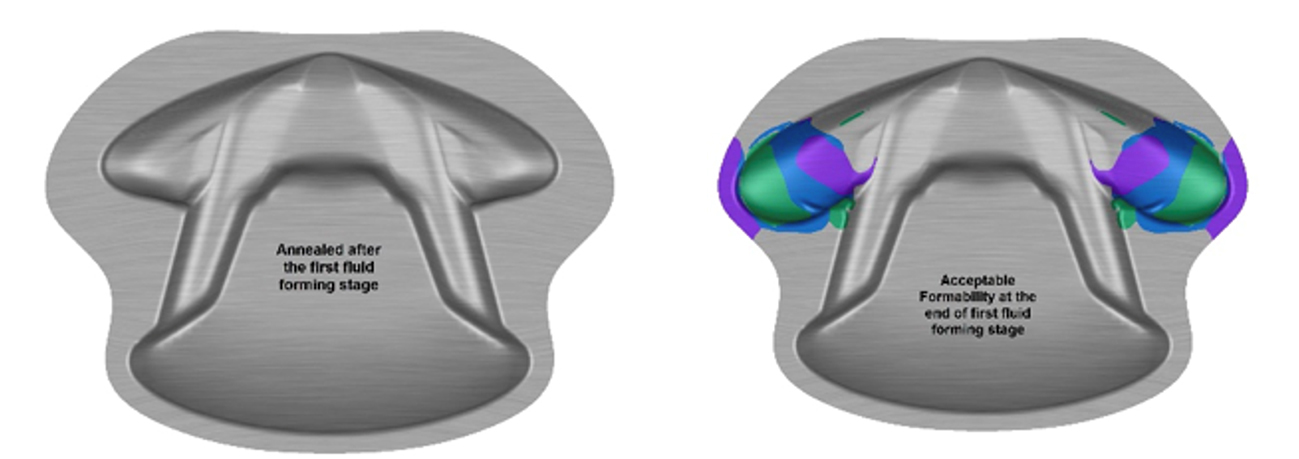
Check out these short simulation animations showing progression of the fluid forming process through the first and second forming stages with the intermediate anneal.
View more information about the FluidForming Metal Forming Process, and refer to additional case studies here.

ABOUT FluidForming Americas
Established in the United States 2014, FluidForming Americas LLC serves industry-leading manufacturers. FluidForming is a Six Sigma metal forming solution for rapid prototyping and advanced manufacturing. Headquartered 50 miles northeast of Nashville, TN, FluidForming Americas is a member of the Precision Metal Forming Association and is AS9100 Rev D, ISO 9001:2015 certified.
FOR MORE INFORMATION
Contact:
FluidForming Americas, LLC.
800-497-3545
info@ffamericas.com


?")


