
Make sure to include skid lines as part of your analysis method
A product that looks good sells well — and a product that looks classy sells even better.
In addition to the functional quality of a car, what catches the consumer’s attention are the car’s aesthetics, providing an impactful visual signature. For this reason, it’s critical for manufacturers to make products that are appealing to the eye. To that end, sheet metal product manufacturers need to manage issues surrounding surface lows, wrinkles, and skid lines on the final product’s class-A surfaces.
What Is a Skid Line?
Skid lines represent damage to the sheet metal caused by dragging the sheet against a tool. The ensuing damage is clearly visible in the form of scratch marks on the finished part surface.
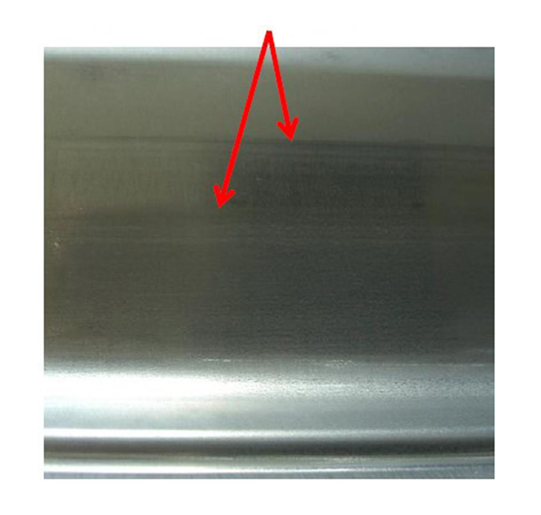
Fig. 1: Die side scratch marks due to die radius and drawbead influence
This type of defect is unavoidable in many cases where material flow is required to form the part. Therefore, the process design must keep these defects in mind to manage the flow and understand the resulting quality. The result of several skid lines occurring in simulation can be seen in Fig 2 below.
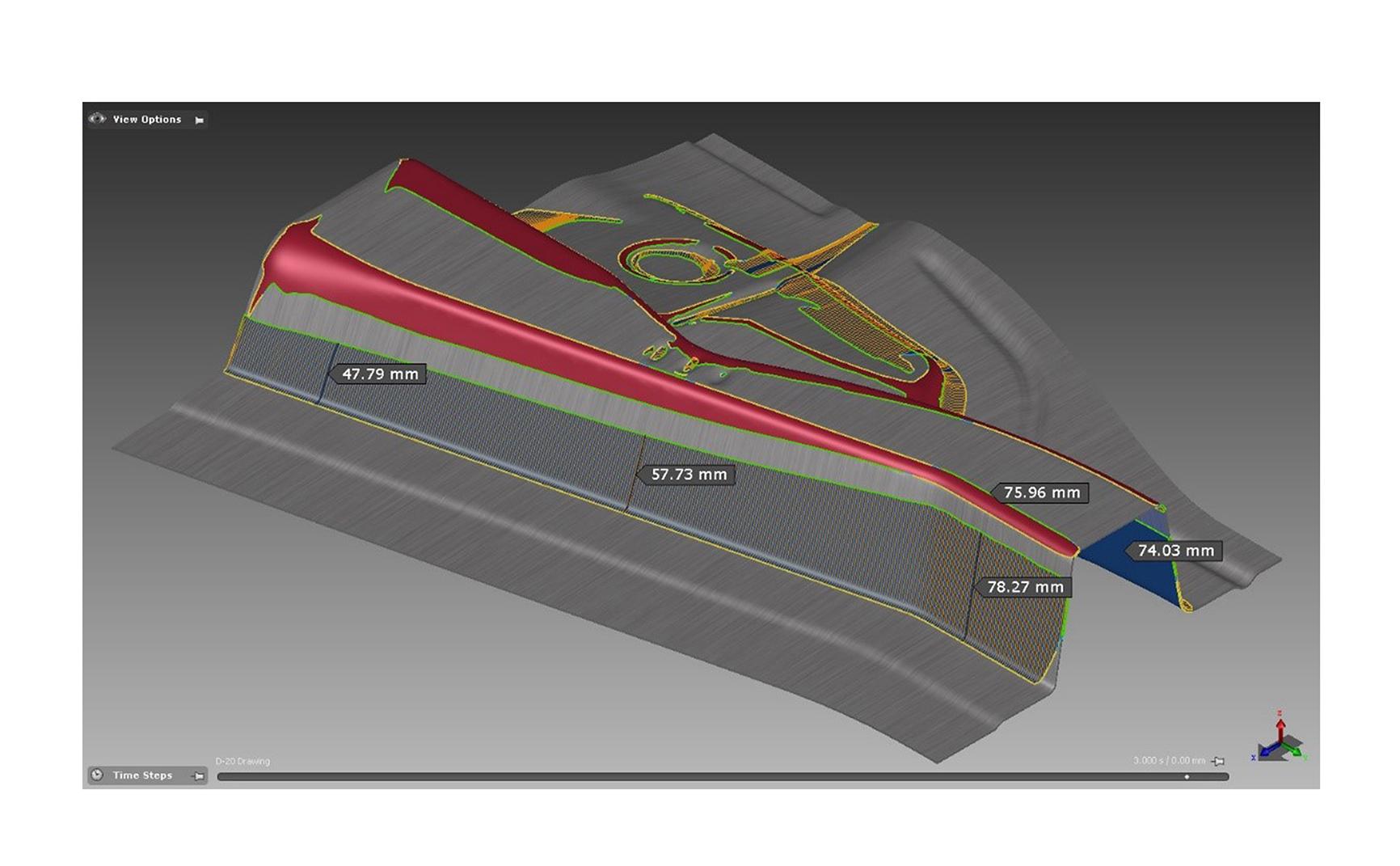
Fig. 2: Skid lines shown in AutoForm
How to Mitigate Skid Lines?
A skid line is caused by the sheet moving over a feature line on a tool surface. This can be mitigated by controlling material flow in a couple of ways: 1. An addendum design that prevents metal movement at the feature line by balancing the tension on each side. 2. Using beads and/or binder spotting to control the sheet’s movements to the same end. There are some basic steps to design the process with these factors in mind, but these can be evaluated with more confidence using a well-prepared simulation. AutoForm provides an automatic method to predict the occurrence of skid lines on the sheet metal and has been proven to correlate well with actual parts. In addition to this automatic method, the user can also add a tool line manually on any of the individual tools to predict the skid lines caused by that tool in a particular area of the sheet.
AutoForm requires two input criteria to predict a skid line on sheet metal: radius and pressure. The tool geometry is analyzed using the largest allowable radius that will not lead to a skid line. Any radius smaller than the input value that touches the sheet metal could satisfy the first condition. If the pressure exerted by the tool on the sheet metal is above the specified minimum limit and the tool radius is smaller than specified, skid line damage may be expected during forming if the material is also moving across the tool. In Fig 3 below, a section view of metal flow shows the start point (yellow) and current location (green) of a skid line.
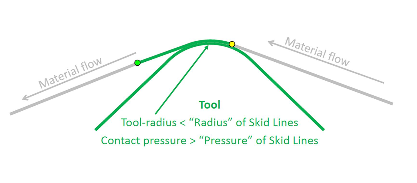
Fig. 3: Looking at material flow
AutoForm provides a recommended value for each of these criteria, serving as a good correlation for many customers. However, customers are also recommended to use recently concluded quality data to correlate the results and come up with a set of values for radius and pressure that will predict skid lines based on experience/history as well as the desired quality level. Appearance quality is a subjective assessment; a customer’s unique quality requirements will determine the final criteria for your appraisal.
Skid line assessment is a high-level task. The designer must be sure that all prior work is accurate and that input parameters, material, and process geometry all represent the real physical tools. Tips on those factors can be found in other blog posts on www.Formingworld.com such as: Basic Simulation Accuracy Requirements and the AutoForm Accuracy Footprint and How Can You Prove Accuracy in Sheet Metal Simulation? The Principle of the Accuracy Footprint Unveiled. If your simulations are well prepared, you will be able to accurately predict the location of skid lines in your processes.


?")


