No More Splits for New Parts for the New Ford Transit Model
In this blog post we interview Ford Otosan’s Die Process Supervisor Cem Bilgili who oversaw the design and tryout of the first ever aluminum parts for the new Ford Transit. Cracks arose in production for the hood inner assembly despite initial simulations clearing the part. Those simulations had applied a fixed friction coefficient of 0.12. It was only upon switching to an advanced friction model that Ford generated an accurate stamping simulation, correctly predicting those cracks in tryout. See the full story in pictures below!
At Ford’s production in Turkey their first run of simulations did not indicate any risks for splits, offering a full green simulation of the aluminum part. The Ford Transit is their latest model, not yet released. The part in question was its’ hood inner and outer assembly. Cem said, “This is one of the parts regularly made with steel, whereas now we have started to use aluminum in order to advance our lightweighting plans. In fact, this was the very first time we have ever used aluminum for the Ford Transit model. Ford Europe and Ford North America provided some of their experience on recommended friction settings in stamping simulations. A fixed friction coefficient of 0.12 was decided to use, a common value used in industry.”

Fig. 1 Green simulation using a fixed coefficient of friction (left) and the splits in tryout (right).
Cem continued “The engineers carried out forming simulations with the recommended friction settings. Using these settings, we arrived at an initial green simulation which included springback compensation. See Figure 1. By all accounts the forming appeared “safe.” We naturally machined the dies accordingly.”
“However, upon first tryout we were faced with an unexpected pair of cracks on the inner panel. See the right image in Figure 1. At first we assumed it must be just a tryout issue, and that maybe the problem had arisen from spotting etc. Our team tried to solve the issue by checking the dies at the press. However, and frustratingly, the same result continued over a three week period. When you consider we work two shifts per day on the same part the cost start to mount up significantly. Using time-tested experience, our tryout team attempted many things. The splits kept occurring in the troubled area. Nothing seemed to work until they applied additional oil to sheet. It became clear to use that the tribological behavior strongly influences the aluminum part quality.”
TriboForm’s Jan Harman Wiebenga joined us to share why is so aluminum sensitive to friction and lubrication, saying “In comparison to steel, aluminum is relatively soft, with lower formability. As a result it’s more sensitive to friction,” adding “because of this the tool surfaces may also need to be treated differently compared to when dealing with steel. It may require additional polishing or treatments of the tool surfaces.” Cem confirmed, saying “Indeed, at Ford we mostly don’t to use scrap-cutters at the die, because aluminum is more problematic than steel.”
Cem continues “At Ford we had already heard about the advanced friction model with TriboForm’s approach and reputation, especially in friction sensitive process, so the request to test their software came from our side to further investigate this friction and lubrication effect. The simulation result including TriboForm directly agreed to the try-out results, showing the occurrence of splits.” See Figure 2.

Fig. 2 Simulation result including TriboForm (right) agrees to the initial try-out results (right) both showing the occurrence of splits.
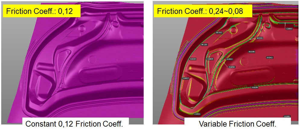
Fig. 3 A standart simulation with a constant coefficient of friction (left) and a simulation including TriboForm whereby the friction varies locally and in time (right).
Jan Harmen elaborated, “What you see in a standard simulation, set with a friction coefficient of 0.12, is that the friction between the tool and sheet is constant across the whole surface of the panel. See Figure 3. This simply is not reality. If you look at the right image in Figure 3 you’ll see variable friction coefficients at work when using the TriboForm Plug-In. Now the friction truly varies across all regions of the part. At the geometrical drawbeads you can clearly see the effect of the relatively high pressure on the frictional behavior. Also looking at the relative sliding velocity of the material through the drawbead you see a decrease of the frictional behavior. In the region where the split occurs, the friction is relatively high due to the local low pressure and sliding velocity. The local stretching in this area of the part is in fact dominated by the draw-in of the part, so the frictional behavior was geometrically draw beads.”
Cem added “When we saw the friction results at Ford we were quite surprised, seeing that we had always set a fixed friction coefficient value between 0.12 and 0.15 in general. Upon seeing the varying friction value on the sheet surface the penny dropped and we immediately knew the cause of our splits. A lesson was learned by our organization and we knew it was now necessary to make an investment in to purchasing the TriboForm software, especially considering our plan to increase the use of aluminum.”

Fig. 4 The second drawbead was locally removed based on the new simulation.
Cem said, “With the improved stamping simulation that included the TriboForm Plug-In, we could now reverse engineer the split issue. See Figure 2. We realized the quickest way to solve the issue was to remove the second draw bead (as seen in Figure 4). We applied this modification to the die and repeated the try out. As you can see in Figure 4, the part came out perfectly without any splits.”
You can join the full presentation on this project at Automotive Circle.
By: Cem Bilgili, Ford & Volkan Karakus, AutoForm.
New readers, if you sign up for our blog you’ll get a once per month update on our latest posts! We’ll never send you marketing emails.


