
Introduction
In the quest for improved competitiveness, industries are constantly seeking effective methods to reduce costs and time in their manufacturing processes and operations. To achieve this goal, many companies are adopting unconventional and more competitive production methods. Against this backdrop, Tecumseh do Brasil, in collaboration with AutoForm and TechnNova, seeks to conduct a feasibility study to explore the potential of using the hydroforming process instead of conventional stamping for producing hermetic compressor housings. This study will be conducted through numerical simulations, and the aim is to enhance the efficiency and competitiveness of the production process.
Methodology
To ensure that the hydroforming process simulations were accurate, we needed to first understand the conventional stamping process currently used for manufacturing hermetic compressors at Tecumseh.
By comparing the simulation results of the conventional process to the lab results of actual specimens, we were able to validate the hydroforming process and compare their feasibilities. Our initial step in the simulation process was to characterize the material to validate the thinning.
We established the following two methodology lines:
- Lab methodology
- Numerical simulation methodology
Lab methodology
The compressor housing was obtained from the stamping stage and later used for laboratory analysis in a simulation. The objective of this stage was to analyze the thickness of the housing and determine the percentage of thinning in different regions.
This analysis was carried out in two parts:
- Analysis of the stamping process
- Analysis of thinning along the housing
For each specimen, two housings were cut (as shown in Figure 1), and their thickness was measured at 11 different points to identify critical regions (as depicted in Figure 2).
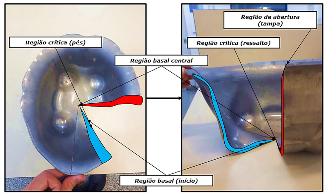
Figure 1: Cutting regions for thinning analysis
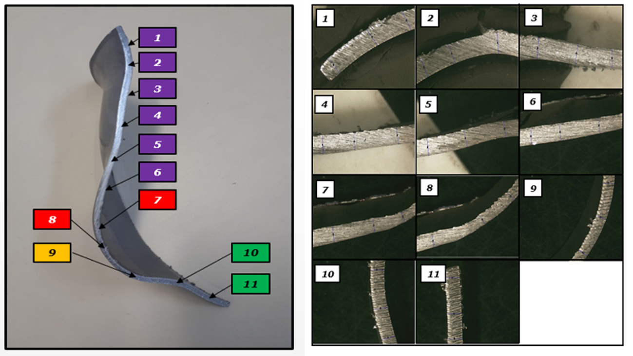
Figure 2: Regions of analysis (thinning)
Numerical simulation methodology
After conducting laboratory analysis, three simulations were performed to compare the two processes, as described below:
- Conventional Process simulation: This simulation utilized the stamping process currently used in production (refer to Figure 3).
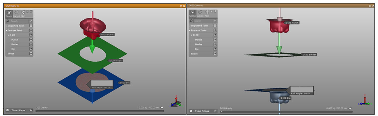
Figure 3: Setup of punch, blankholder and die for the intermediate forming stage of the housing
2. Alternative conventional process simulation: To conduct this simulation, the initial procedure followed the conventional process, with the same material and imported geometry. However, a modification was made to the radius of the housing cover on the punch and the die. This modification was necessary to prevent sealing problems that could occur during the hydroforming process at the final stage of tool closure, as the die radius was too large.
3. Hydroforming process simulation – Hydromechanical deep drawing: For this numerical modeling of the hydroforming process, the housing material and its imported geometry remained the same as in the previous processes. The geometry consisted of a preliminary stage for calibrating the final geometry, eliminating one of the manufacturing stages in the conventional process.
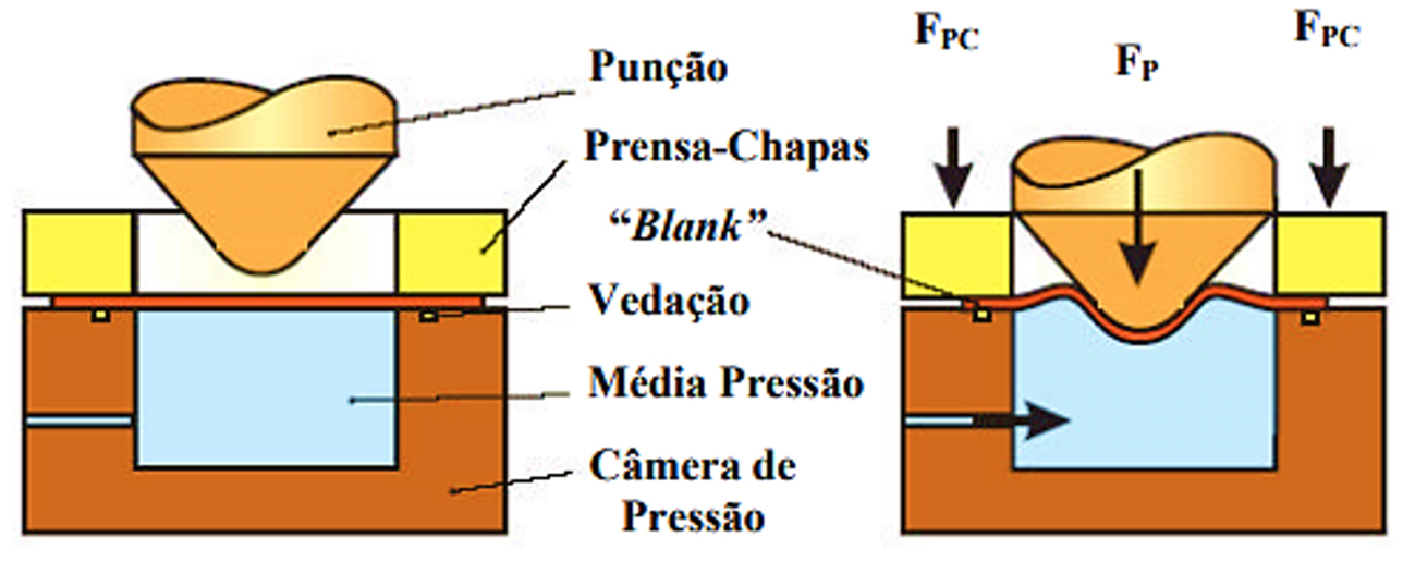
Figure 4: Hydromechanical deep drawing [12]
Results of the study
Lab analysis results
In the area starting from the compressor cover and extending to the foot region, a significant thinning of up to 40.79% relative to the nominal thickness of the sheet was observed. In contrast, the maximum thinning in the compressor shoulder region was only 25.73%.
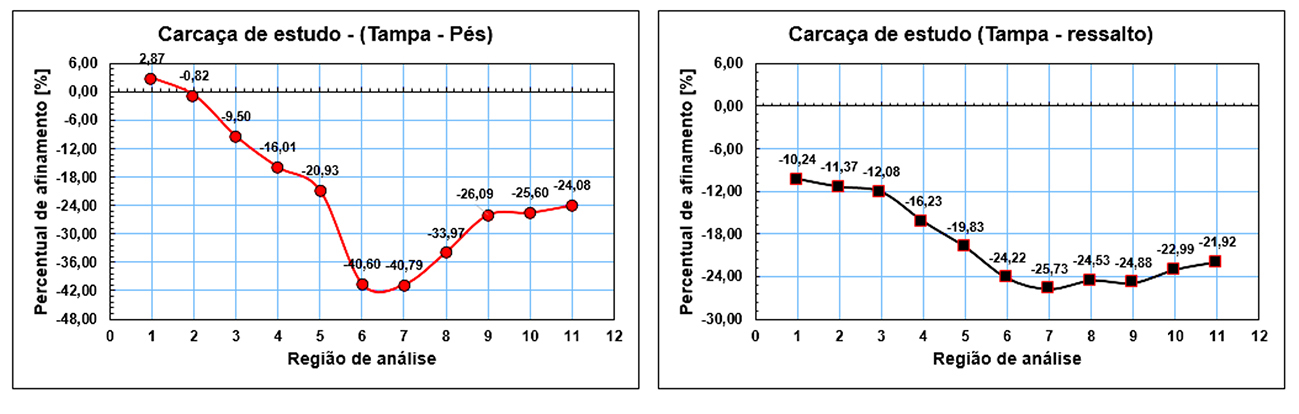
Figure 5: On the left, thinning values obtained from the Cover-Feet section. On the right, values obtained from the Cover-Shoulder section.
Simulation results
FLC curves and thickness reduction – Conventional and alternative conventional process
The conventional deep drawing simulation showed several highly critical regions, most of which were located at the compressor feet. In contrast, the alternative process demonstrated improved material formability utilization compared to the traditional process despite reducing the radius, indicating high friction in the radius region.
Thicknesses in the highly critical regions were between 30% and 40% less than the nominal thickness in the conventional process and between 20% and 30% in the alternative conventional process, demonstrating process improvement.
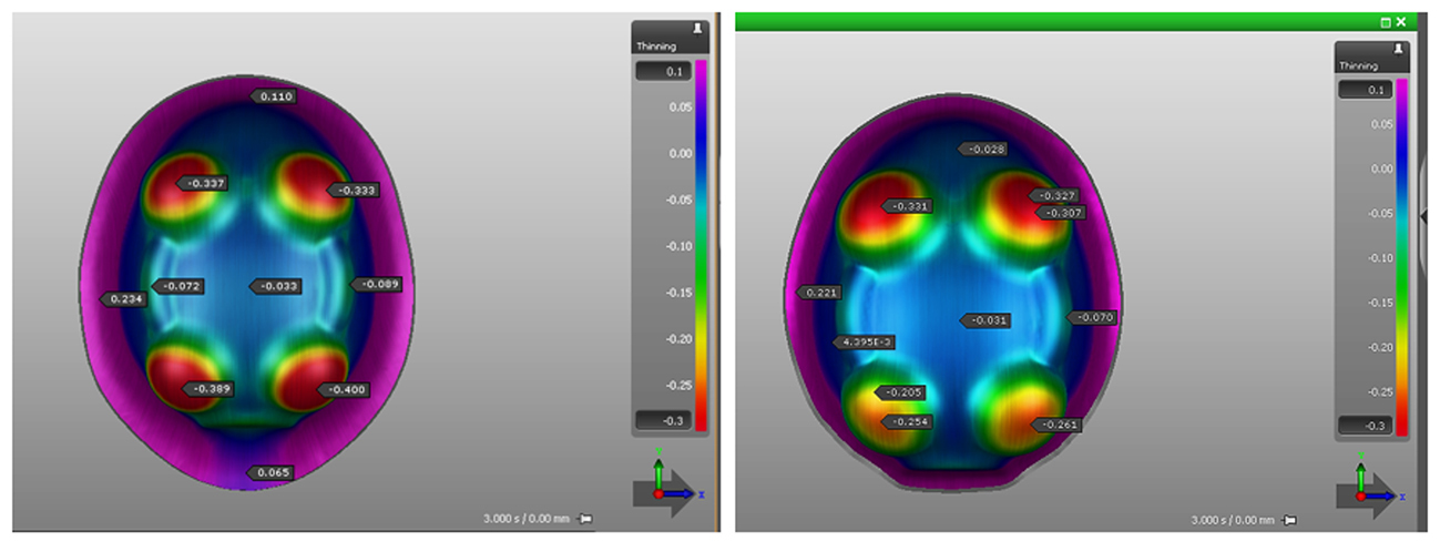
Figure 6: Thickness reduction in the a) conventional and b) alternative conventional processes
FLC curves and thickness reduction – Hydroforming process
Hydromechanical deep drawing required determination of the maximum pressure throughout the process. Simulations were conducted at four different pressures of 10, 20, 30, and 40 bar to determine the optimal pressure, with the best results obtained at 10 bar. Thinning values at 10 bar showed a reduction between 20% and 25% relative to the nominal thickness, representing an improvement over the conventional process.
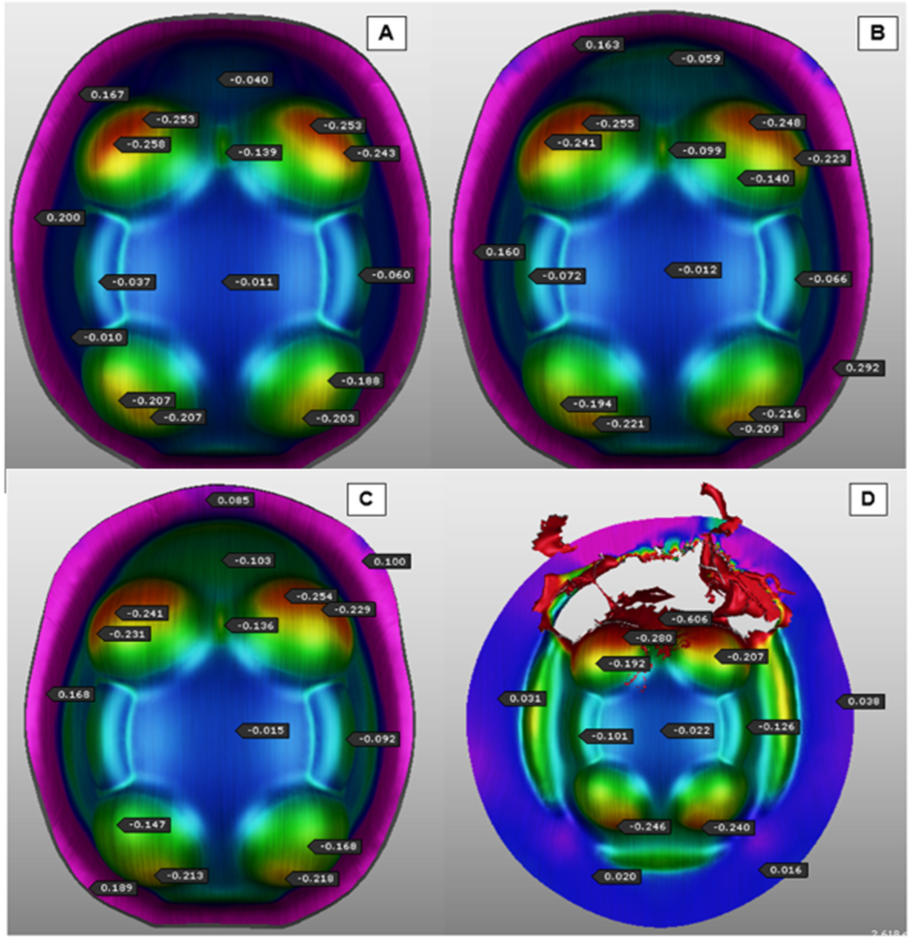
Figure 7: Thickness reduction at different pressures: a) 10 bar, b) 20 bar, c) 30 bar, d) 50 bar
Conclusions
Based on the case study, we can conclude the following:
- The hydroforming process is a better alternative to the conventional deep drawing process as it improves material formability utilization, as demonstrated by lower thinning values.
- The hydroforming process eliminates one manufacturing stage compared to the stamping process, reducing production time and cost.
- Optimal results were obtained at a pressure of 10 bar, with critical regions showing a thinning of only 20%, indicating improved product quality.
- The use of AutoForm as an analysis tool provided a detailed and comprehensive analysis of the proposed hydroforming process, highlighting its pros and cons and enabling the selection of optimal parameters.
References:
White Paper: “HYDROFORMING PROCESS NUMERICAL MODEL APPLIED TO HERMETIC COMPRESSOR HOUSINGS.” By Erlifas Moreira Rocha, Universidade Federal do Rio Grande (FURG), Prof. EngD João Henrique Corrêa de Souza, Universidade Federal do Rio Grande (FURG).


?")


