
Sports cars are the epitome of extreme engineering, with their unique design requirements making them particularly challenging to build. The body-in-white (BiW) of sports cars, in particular, poses difficulties due to its complex curvature. But what happens when you attempt to reproduce a sports car that was designed over six decades ago using state-of-the-art stamping simulation technologies?
In this article, we will learn about how during the COVID pandemic, MW Designs from the UK was hired to provide engineering services to create a replica of a 1960’s sports car. Their customer was responsible for stamping the panels for small-run specialist which produces luxury electric replica sports cars, which include models featured in Hollywood action movies. Instead of revealing the actual car model used in the project, we have replaced it with a 1960’s Ford Shelby Cobra which features a very similar body. This article will explore the process that MW Designs used to replicate the car’s curvy BiW.
The First Challenge: No Separate Panel Designs
The first significant hurdle for MW Designs to provide engineering services to the customer arose when they discovered that there were no split lines in the BiW to start with. They did not have access to any information regarding the number and placement of split lines from the original 1960s model.
Therefore, the team’s starting point was to obtain an original vehicle (in this case a Ford Shelby Cobra), conduct a 3D laser scan of the entire vehicle, and slightly reduce its’ size, as was the customer request for their luxury electric version, to create the starting geometry.
Using AutoForm, MW Designs set out to identify the optimal locations to divide the entire car body into separate panels. They decided they needed to determine which split lines would result in the ideal set of individual panels that required the fewest forming operations and the least amount of joining to assemble the final product. This raised a question because it is not every day that the team working on individual panels as a Tier 1 supplier to an OEM get to impact this step.
Therefore, an interesting lesson may be learnt here. Deciding where to split the BiW would be critical since splitting it one way might create more work later, while creating larger panels in other areas could reduce the amount of work required to achieve the same outcome.
By conducting forming feasibility studies and examining each split line variation and panel individually, the team could determine which split lines would result in the most efficient assembly process. In essence, it was akin to dividing a picture into pieces to determine the most straightforward way to assemble a puzzle with the fewest components.
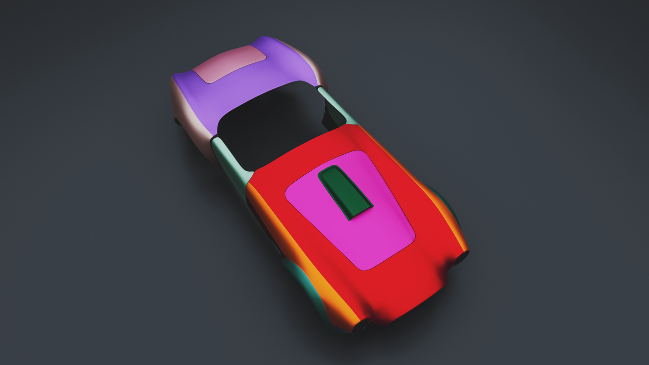
Fig. 1: Split of 30 panels was the minimum feasible number of panels.
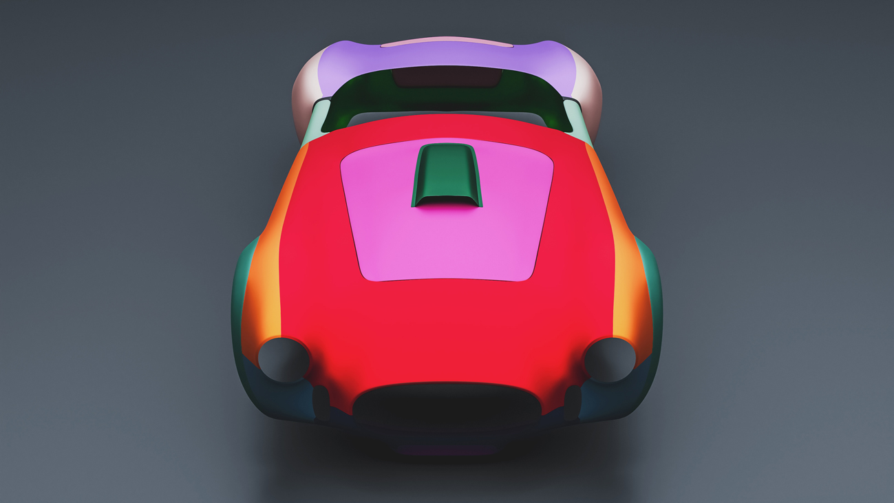
Fig. 2: Hood panel extends to create wielding seam along top of fender.
The Optimal Number of Parts
When the team attempted to split the scanned vehicle into as few panels as possible it came down to intelligent thinking and understanding assemblies.
For example, they explored the option of creating the entire rear portion, including the clamshell and the wings, as a single unit. However, this approach proved difficult, as forming simulations revealed excessive wrinkles in the rear of the inner wings. To address this issue, the team divided the rear panel into a central section and two rear wings.
The same process was followed for the front panel. Initially, they aimed to create the front bonnet, wings, and nose cone from a single piece. However, AutoForm simulations predicted similar wrinkling issues as with the rear clamshell. Therefore, they divided the front panel into upper wings and a central part, which served as the main bonnet and featured the inside of the wings as one piece.
Even after fragmenting the front panel at the wings, the central section remained quite substantial. In fact, it was essentially the entire front panel without the outer wings.
The decision to split the panels at the top of the wings had little to do with simulation results. Instead, it was done to achieve a longer, more well-defined seam for welding purposes. Longer seams were easier to TIG weld and required less hand finishing.
After positioning the panels, some handwork was necessary to achieve the final finish of critical areas. Handcrafting certain parts is standard in traditional and high-value manufacturing for perfecting the final form after the stamping process. The team used traditional hammer and dolly sets to accomplish this task.
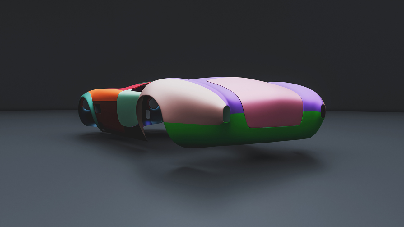
Fig. 3: View from rear angle.
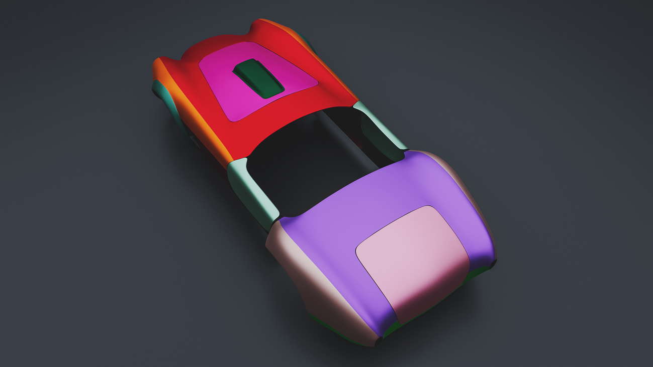
Fig. 4: Wielding seam runs along top at the rear also making a wider center panel.
Optimizing Material & Achieving Deadlines during COVID
Despite COVID restrictions, the anonymous customer who had to stamp the panels based on MW Design’s engineering work, was determined to deliver on time. They needed to acquire castings, manufacture polys, and transport everything to their shop within a specific timeline for producing panels. It appeared that they might not be able to meet the deadline as they had to machine, embed, press, and remove the parts. Nonetheless, the factory managed to complete the production of 120 cars during the pandemic.
Through the simulation and tryout processes, the customer was able to save time, which compensated for other delays that were outside the scope of MW Designs’ simulation team but were crucial to the customer. In fact, thanks to simulation, many of the BiW processes were completed much earlier than expected.
As a result, our customer was pleased that they were able to deliver on their promises despite the constraints on time and money during a difficult period. Simulation also provided other benefits, such as material selection. Initially, the customer was recommended a cheaper aluminum alloy for the body-in-white, but our simulations showed that it was not suitable for working with presses. We helped the customer select a more appropriate alloy, and they chose the 5754 aluminum instead.
Another benefit of simulation was reducing the number of parts required for the complete assembly. The original vehicle needed around 70 distinct panels, but our feasibility analysis through simulation helped to reduce the number of panels to just 30. This significantly reduced the complexity and time needed for manufacturing.
Tryout Successfully Produced Engineered Simulation Parts
The pressing tools used were what we call “low volume tools.” They were of low specification and essentially comprised an upper die, a panel, a binder, and a three-piece tool. There was no guiding mechanism. Despite this, the tryout stage was a success.
The parts produced from the first tryout press were almost perfect. Minor manual adjustments resulted in near-perfect parts in the second tryout and perfect parts in the third. In many cases, the panels were good enough in the first tryout because the team built what was engineered in the simulation.
The tryout stage doesn’t need to be lengthy and resource-intensive. Teams may spend weeks or even months attempting to create a single functional part off the tool. However, the upfront engineering saved a lot of time and effort in the tryout stage. The end customer who would sell the electric replicas received the parts quickly, pleasing all stakeholders involved.
Conclusion
A robust and reliable simulation provides numerous benefits, no matter the application. In this case, we witnessed how it can aid in the redesign of a classic sports car. The process saved time, cost, and effort involved in producing these demanding designs while reducing the number of panels required for the sports car to just thirty. This was not feasible sixty years ago when the original car was built. Today, we can build it better than ever before.


?")


