
Early Feasibility: Doing it Right (or Wrong) From the Start
This blog post emerged from an urgent call we received from one of our customers. As a result, AutoForm Technical Account Manager Stephan Küper delves into the significance of conducting thorough early feasibility studies and how they relate to the concept of “too little, too late.” If a viable strategy for springback compensation has already been achieved during the initial stages of part and process feasibility, the tryout team can avoid significant wastage of time and cost. However, the question is: Are you fully implementing this principle?
Here lies the crux of the matter: Rectifying issues that could have been avoided often necessitates changes to the part geometry. And let’s be honest, this demands substantial effort and incurs high costs when done at the later stages of the tryout process. You’ve witnessed this scenario at the press table and heard your tryout team say, “The software user has no clue about reality.”
All of this could have been prevented. But how did such a predicament originate?
It all begins with the primary objective of the part feasibility team. One of their tasks is to minimize further modifications to the part geometry during method planning and die design. As a common practice today, they strive to ensure that the designed part geometry can be manufactured without encountering cracks and wrinkles after passing the part feasibility check. Unfortunately, their goal is simply to get the part design approved.
“No cracks, no wrinkles, so I’ll give it the green light. Job done.”
Consequently, customers often face issues when assessing springback. Compensatory measures are now required for the tool, but they are initiated too late in the process. Frequent issues in this context include the absence of robustness evaluations for springback and backdrafts in the tools after compensation, leading to excessive springback. Overall, avoiding early work comes at a cost, and its repercussions can extend over several weeks.
This is precisely what happened to our customer, and they realized it could happen again.
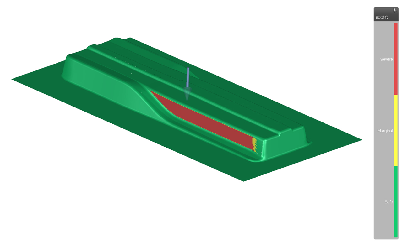
Fig. 1: Backdraft in the drawing tool after springback compensation.
During the feasibility phase, design changes are quite common and carry minimal consequences. Any necessary partial modifications, such as incorporating stiffeners for improved robustness or adjusting wall angles to ensure compensability, can be addressed at this early stage.
On the other hand, when it comes to releasing the part design, it is crucial to consider the process’s robustness and the part’s compensability using a known method.
Furthermore, it is important to clarify that the assessment of compensability is not the initial step in evaluating springback. The primary objective should be to identify the boundary conditions that have the most significant impact on the resulting springback for the part. This can be achieved by calculating springback after each operation and comparing the individual outcomes.
For instance, in Figure 2, it is evident that the high springback values in the flange area at the top left are primarily attributed to the drawing process rather than the flanging process.
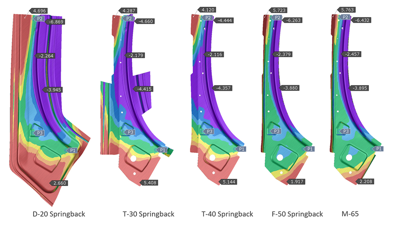
Fig 2: Comparison of springback after each operation.
The second step involves efforts to minimize springback and establish process stability (robustness) to facilitate easier control. Ideally, this would be achieved in a way that eliminates the need for tool compensation.
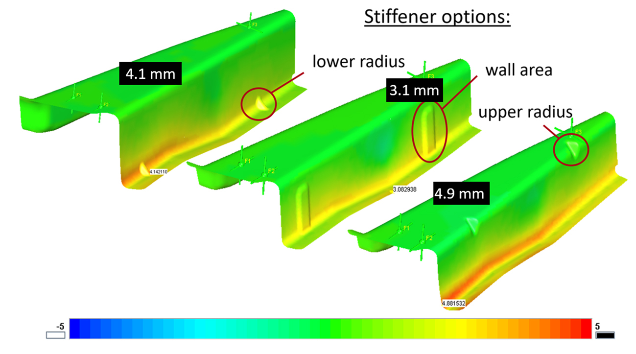
Fig. 3: Investigation of different stiffener options to reduce springback.
The third step is to find an appropriate compensation strategy.
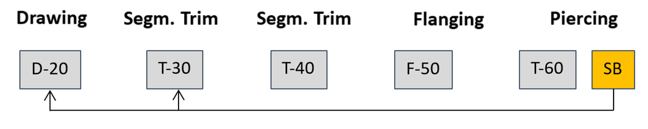
Fig 4: Compensation of the drawing and first trimming operation through the springback result of the final part. This approach is suitable for parts where the last operations have only a minor impact on the springback outcome, such as piercing.
Therefore, for conducting feasibility investigations, it is recommended to use a simplified simulation setup. This allows for checking multiple concepts and comparing the advantages and limitations of each explored option, ultimately enabling the selection of the most suitable one.
Typical characteristics of the setup during the early feasibility phase include:
- Rapid Swift creation of conceptual tool surfaces using AutoForm Die Designer.
- Simulating drawbeads using a substitute model (adaptive line bead) with flattening to assess draw-in and wrinkles during binder closing.
- Ignoring the closing of cutting tools (cutting only), assuming an “optimal” trimming operation without plastic deformation of the sheet.
- Conducting straightforward robustness checks by employing standards and material files to define noise variables.
- Adjusting accuracy settings to expedite the simulation process.
To conclude, the approach described for analyzing springback behavior, process robustness, and compensability during the part and process feasibility phase contributes significantly to the frontloading strategy in virtual product development. Our team guided the customer in conducting robustness analysis in the cloud to troubleshoot the issues they faced. By analyzing the process and suggesting minor changes, we achieved positive results. This success led to the approval of additional AutoForm training, as we recognized the importance of continuous learning to maximize the benefits of our solutions and stay updated with the latest advancements.
Overall, this approach reduces the development time of new products and prevents the need for later changes, thereby enhancing the coordination between development and manufacturing. It’s the small investments that yield significant savings.
And as for the proof in the pudding? Several of our customers have achieved the goal of a one-loop tryout through the use of comprehensive studies. Take, for example, Ford and Saitama Japan, who have successfully employed digital engineering to get it right the first time around.


?")


