
Saving Your Tools from Wear, Tear and Downtime
Your progressive die layout looks great, and your forming outcomes are acceptable, that is, until your tryout team starts grappling with the different forces at work at each station. Your tool center is not aligned to the press center of force. Force imbalance is always an issue for progressive dies. That is why our customers are greatly interested in being able to assess, upfront, the progression of forces from station to station, as well as how balanced these forces are about the center of press.
Progressive die forming allows for high rate of production of complex parts; different operations – trimming, forming, flanging, drawing – take place at different stations, but all under the same ram. With different force requirements at each station, it is difficult to engineer a balance of forces and moments about the center of press.
Force balance is one thing. What happens when moments from these forces, about the press center, and about the X- and Y-axis, are not balanced (see Figure 1 below)? If one station requires excessive force to be applied in one direction, the dies in the next station may not close on the opposite side … such potential imbalances need to be assessed and counter-measured upfront in engineering, and the potential for such incidences need to be handed off as inputs to the tool build team.
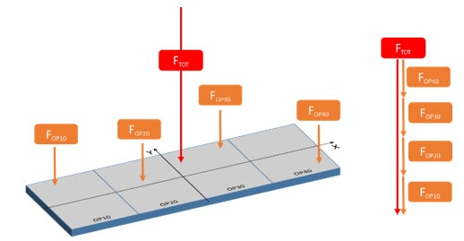
Figure 1: Example of forces distribution per station.
If this is not done, the tryout team is going to face frustration! Ultimately, your entire tool design will be effected by the lack of the knowledge of these forces.
As an example, through upfront calculations in simulation, it is possible to get to know beforehand that reaction forces from the sheet may cause the tool to not close evenly. Consequently, the tool build team can be made aware of the need for spacers to balance loads. Furthermore, the strip may not need to be as tight as originally thought because more room needs to be added for spacers. There are many such examples of what adjustments might need to be made to ensure balancing of forces and moments during operation of the tool.
What might happen if the force center for the die is off 100mm from that of the press? Normally, it is important to mount the die in the press, center on center. If the center point of force is 100mm off then you are literally forcing the press to overcompensate. The press has four slides and four posts; each one of those posts has a guide. If the center of force is off then one or more of these guides is going to have more strain placed upon them as compared to the others. Consider what this means in terms of press wear when the press has made over 100,000 strokes? Your press is going to need more maintenance, and that means more cost, more downtime and therefore loss of production. This needless maintenance can be avoided by digitally running the process, becoming aware of potential problems ahead of time with opportunity for meaningful countermeasures and their digital validation!
One of our customers Fara Stampi Srl stated that they use information from digital engineering and simulation to execute precautionary countermeasures for their tools. They have observed that some tools needed a particular type of coating, based on this information, which saves the tool from wear due to the higher pressures applied at one station. To reduce downtime they have also added a set of screws so they can easily unmount the tool to replace it, which also helps reduce downtime in production. They know which tool will wear out faster than others!
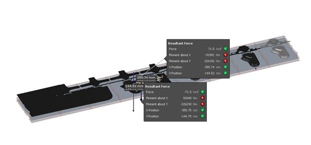
Fig. 2: Force resultants calculated by AutoForm.
At AutoForm we have introduced a method to calculate the forces at work, showing the imbalances and we can determine how far off the forces are from the center of the press so that during the design phase you can become aware of the reality of your process. As a result, you can improve design or foresee changes which must be implemented at each station. Your tryout team or tool manufacturer will find this information invaluable, as they can build the tool according to the actual issues.
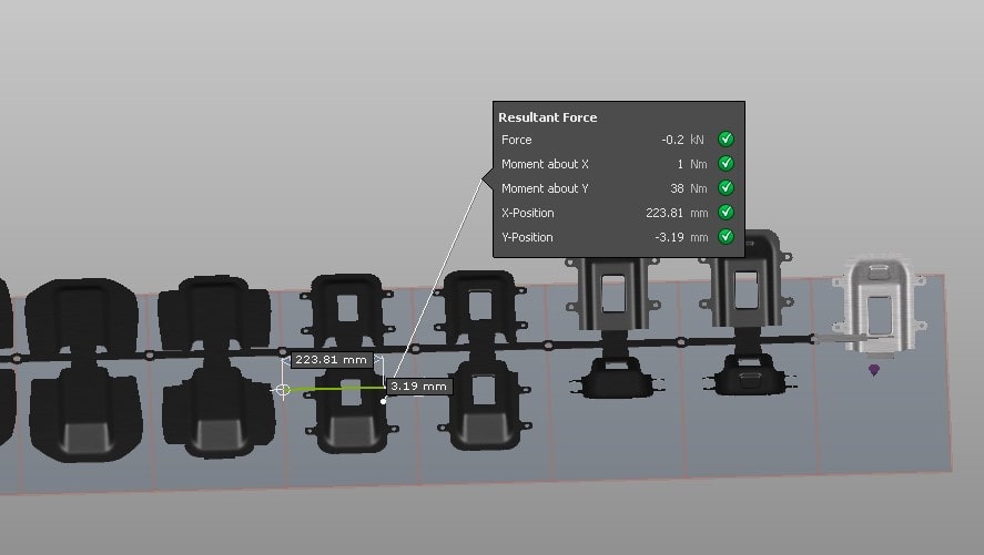
Figure 3: Press Line view of full strip simulation with force moments turned on.
In order to see the full kinematics of the tool, you can create a full strip layout. Within this feature you can see every station at once and how it’s going to play out in the press. There are several things you can do. You can export the full strip as a solid. You can take the entire strip out of AutoForm and bring it into design for validation. This is extremely beneficial for final tool reviews.
An additional feature worth mentioning is the ability to select a narrower coil for closing the distance between stampings. Such a benefit means saving material, but also, you can use this functionality to close the distance between the parts on the coil, making the gap between them as small as possible. This makes for even less material waste around the part. In practice, our customers are taking advantage of this new feature by making the gaps smaller and smaller until it fails and then adopt a safety margin. In this way, you work your way down from your chosen figure to optimize the best trim.
What’s best about all these new features is that they are included in AutoForm, so our customers already have them for free! The best place to learn how to use it in practice is to sign up for one of our AutoForm Base Trainings at a local office near you.


