
The side sill assembly is a crucial car component, contributing to both safety and quality. To meet safety requirements, it is typically constructed from ultra-high strength steel and contains a significant number of welding points (Fig. 1). As a result, controlling the dimensions of the side sill assembly is a challenging task. In this article, we’ll explore how to kick-start the tryout process of a side sill assembly using AutoForm Assembly.
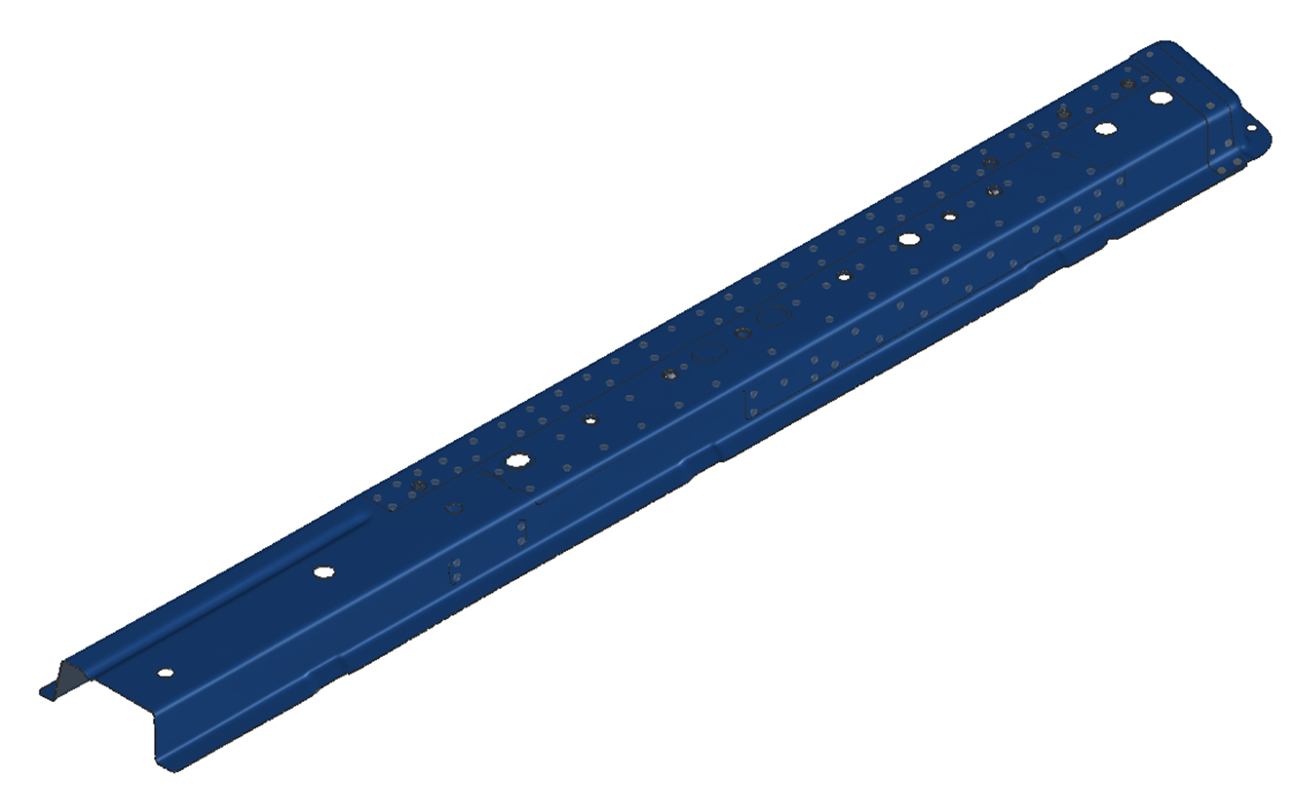
Fig. 1: Welding points distribution
The assembly includes as many as 128 welding points, which are covered through 6 welding operations (see Fig. 2 below).
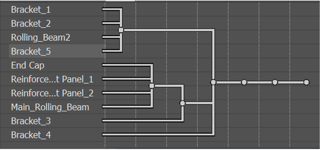
Fig. 2: Welding plan
After several welding tryout loops using the traditional trial-and-error method, we continued to encounter serious dimensional issues. The most notable problem was at the open end of the assembly, where we observed significant twisting, with a +2.5 mm deviation on one side and -1 mm on the other (see Fig. 3).
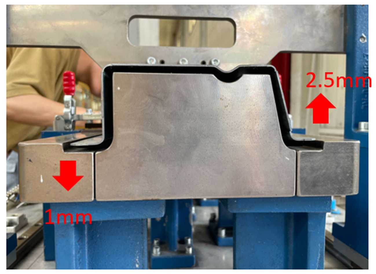
Fig. 3: Dimension deviation after several trial-and-error loops
This indicated that we would not achieve a qualified assembly using traditional tryout methods alone. As a result, we turned to AutoForm Assembly for a numerical analysis of the process.
Step 1: We scanned all the individual panels, simulated the assembly process with the scanned inputs, and obtained results with a significantly higher level of accuracy (see Fig. 4).
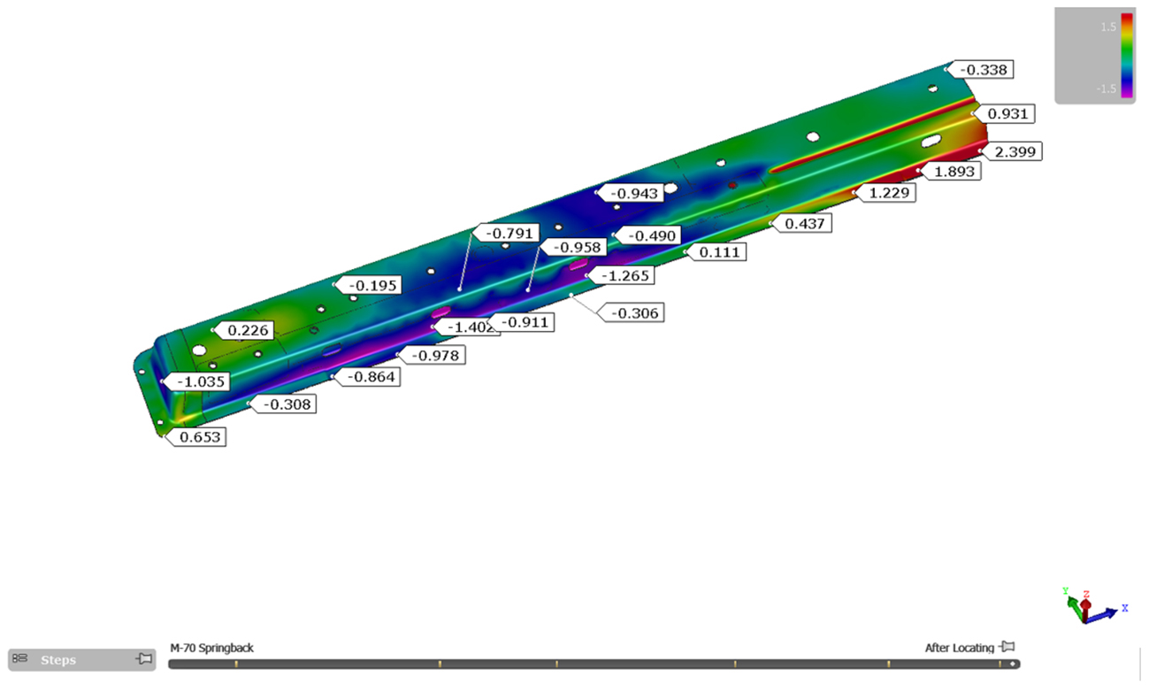
Fig. 4: Simulation results using scanned input
During the virtual assembling analysis, we identified two issues related to the fit between the scanned panels. First, there was interference between the end cap and the main rolling beam at the fillet area (see Fig. 5), caused by the poor dimensions of the end cap. Second, we found a deliberately designed gap of approximately 0.8 mm between the mating surfaces of the small bracket and the rolling beam, which could contribute to harmful distortion in the final assembly (see Fig. 6).
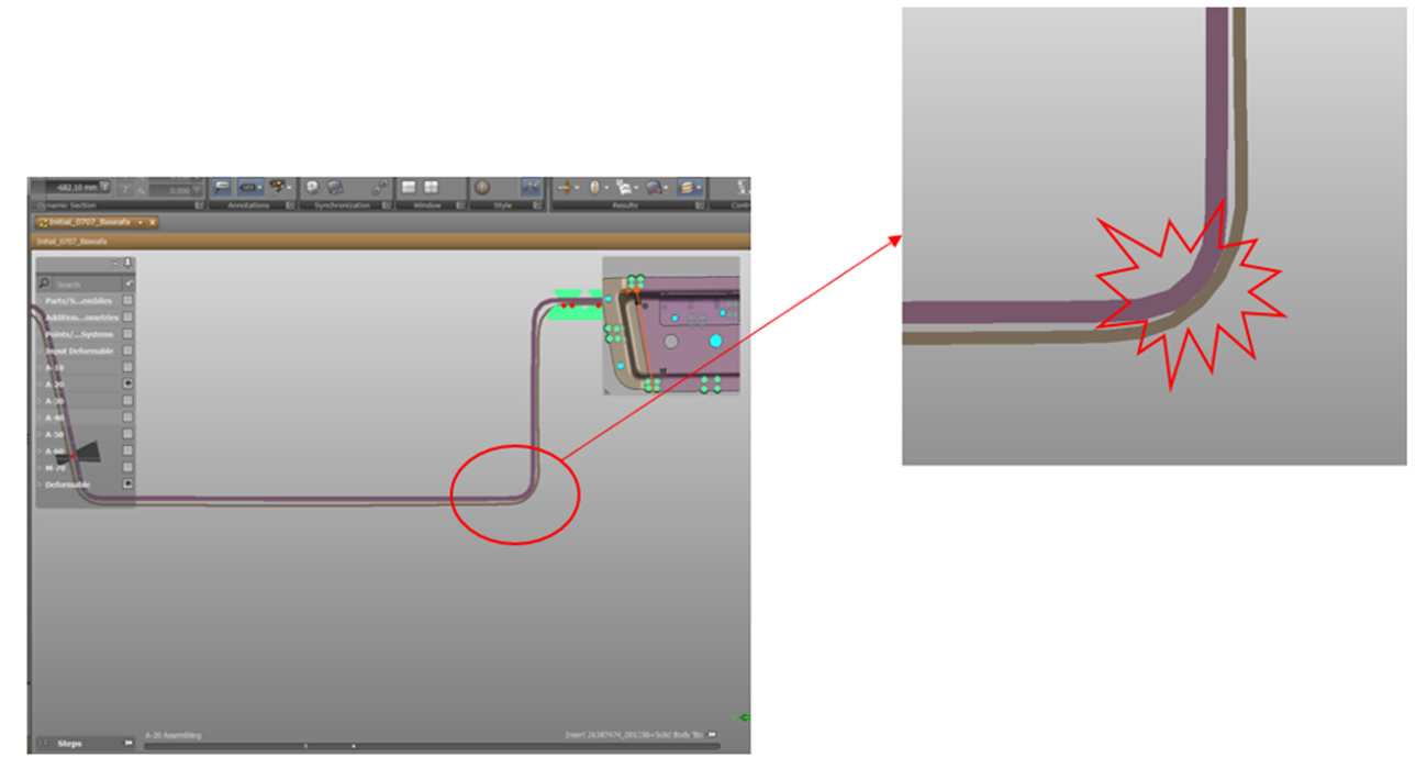
Fig. 5: Interference between end cap and rolling beam
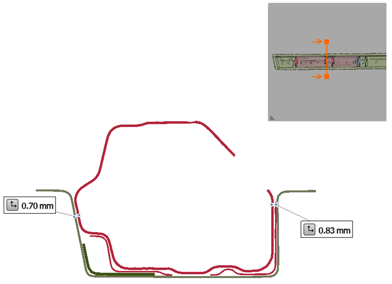
Fig. 6: Deliberately designed gap between mating surfaces
Step 2: We selected two component panels (the main rolling beam and the end cap) as targets for compensation and applied compensations using AutoForm Assembly. The final compensation amounts and results are shown in Fig. 7 and Fig. 8.
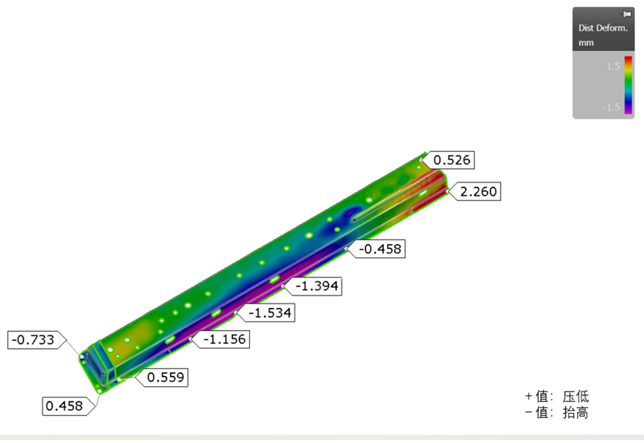
Fig. 7: Compensation amount distribution
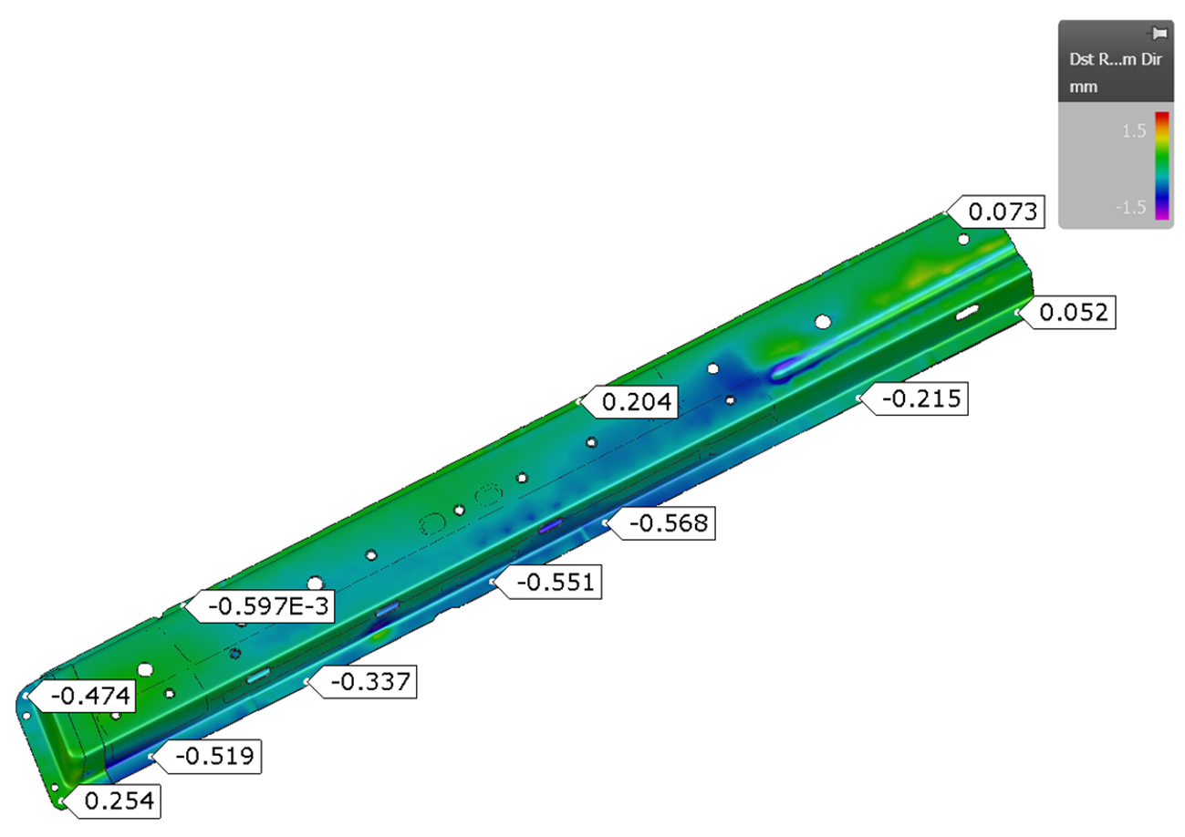
Fig. 8: Results after compensation
Based on the simulation results, we implemented three corrective measures in the part design and for the individual panels:
1. Compensated the rolling beam and end cap.
2. Corrected the interference area of the end cap.
3. Adjusted the tolerance specifications of the small bracket and modified the dimensions of the real panel to minimize the assembly gap between mating surfaces.
As a result, we achieved an acceptable welding assembly, with most dimensions falling within the ±0.8 mm tolerance range. Only one testing point showed a deviation of nearly 1 mm (see Fig. 9). This level of dimensional accuracy was sufficient for further car manufacturing, and no further optimization was needed.
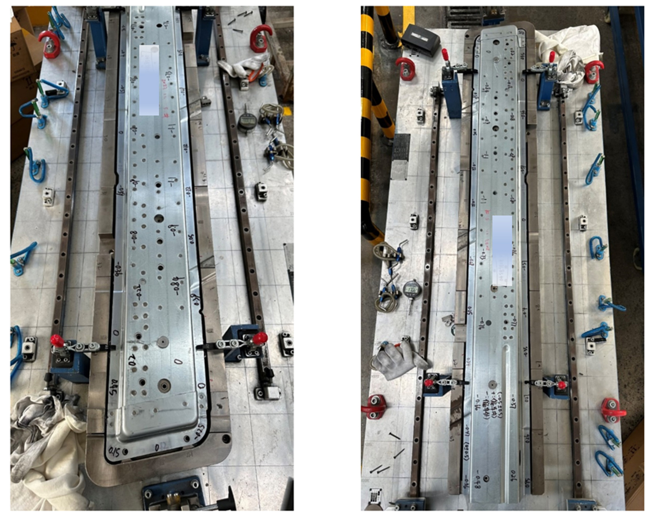
Fig. 9: Final assembly state after applying countermeasures
Conclusion:
1. AutoForm Assembly can be effectively used to analyze side sill assemblies composed of multiple ultra-high strength steel panels.
2. Potential twisting caused by poor panels dimensions and dense welding points can be predicted and analyzed.
3. AutoForm Assembly provides valuable insights to kick-start the tryout process of side sill assemblies.


?")


