Has it ever happened to you? A simulation report shows a design is safe – green with no splitting failures, no red or yellow colored areas. But when reviewing the design file, you find issues that were not reported or identified. Or when an issue is observed, you find spend additional time scrutinizing the simulation settings to see if the issue is real, or an artifact of erroneous simulation settings. How frustrating is it when you can’t replicate the results reported in earlier design iterations, or find it difficult to identify the change that led to the difference in predictions? Does that improve your confidence in simulation?

You can’t Photoshop your way to a passing process.
Simulation computational and modeling accuracy is a large topic, but the importance of consistent definition of appropriate company tooling standards and engineering settings is often overlooked. As the saying goes, “garbage in, garbage out”; no matter how advanced simulation technology is, if users are not able to consistently enter appropriate inputs and apply reliable interpretation criteria, all results remain suspect.
Die process engineers and method planners try many things to address forming issues that are identified during simulation; multiple design iterations and simulation runs quickly litter drives with terabytes of data for review. Forming issues can go unidentified because people did not look at the right location, failed to view a necessary output variable, or modeled a process that did not represent the production intent of the real tools. Without the means to assure consistent application of simulation parameters, design guidelines, and interpretation of results, the outcomes of performing metal forming simulation will still fall short of our goals. Peugeot Citroen (Peugeot S.A or PSA) has deployed standards that they use to assure that metal forming simulations are defined, performed, and evaluated consistently for their products and processes.
Standard values for die face
Take, for example, the generation of a die face for draw and initial forming operations. Many organizations have die design standards that govern geometry used to define die face. Minimum wall angles, maximum trim angles, and minimum tooling radii are all common tooling settings that guide designers when building geometry for their tools. Organizations may define such standards to assure formability and robust die build conditions, minimize material utilization, or support other design-for-manufacturability targets.
Standard values for die face parameters could hypothetically include a standard wall angle and die radius: 12.0° open wall and 6.0mm radii. Defining standard geometry also populates the interface with an initial preferred value and indicates any value that differs from the value that is entered. The user has the flexibility to change the values for these die face parameters; however, any change should be easily recognized. This ensures that users can easily identify any place they have deviated from norms established by their organization.

A defined standard for tooling geometry, such as wall angle and die radius for use in defining die face surfaces
If a modification of any value defined with a standard occurs, the parameters will be highlighted for ease of identification and can be reset to the standard values easily. Using this functionality, metal forming engineers at PSA are able to guarantee that only die face parameters that have been approved by the automaker will be used; both internally in their simulation department as well as at suppliers (values represented in the attached images have been altered from their corporate standards). Taking the definition of standards one step further, an organization could also elect to lock (Lck) a given value to prevent any excesses that it might wish to avoid altering. In the case above, the maximum allowed punch opening (Max PO) width is locked at 100mm; users would not be able to input any value greater than 100mm.

Wall angle and die radius that differ from standard are easily identified
Standard values for display and computation

The color scale shown here denotes any values that exceed the thinning range. Any values beyond the limit of 0.25% thinning would otherwise be the same shade red as 0.249%
Another application of standards is also in the performance of results post-processing. In this case, standard values for acceptable minimum and maximum limits for the results value “thinning” can be defined. With a defined standard range for minimum and maximum thinning, it is simple to identify any areas of the stamping that fall outside the defined range. Critical areas with thinning values outside this range are shaded in gray or black.

Specification limits for thinning results
Here standards ensure that result limits will be used consistently during post-processing:
- different designs and their results can be compared more readily
- suppliers can design and analyze faster, because requirements are directly communicated and applied
- reviews are easier once user becomes familiar with the display of outputs determined by standards
Issues Based post-processing
Such standardization of output display is useful to create consistent reporting. But it still requires that the user take the effort and the time to look for issues and then report them. A further step toward streamlined analysis and interpretation is the ability to use standards for evaluation so that the software can be used to automatically detect and identify potential issues.
Standards-based issue detection uses the applied standard to define upper and lower threshold limits for potential forming issues like splitting, wrinkles, draw-in, and springback. The application can be prompted to identify all issues that meet or exceed the definitions contained in the standards. The users can then follow the interface through list of identified issues and determine whether the issue is significant to their engineering process or not. Any issues that the user verifies in the design file are stored within the design file, so that for future iterations, those same areas will continue to be monitored as potential zones for concern.
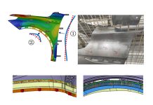
Issues associate with the 3-D view of the results of original design (left), if future iterations resolve the issues those areas will show the improvement(right)
Standards
AutoForm developed standards- and issues-based post-processing to enable users to spend their time more effectively doing what makes them profitable—engineering optimal sheet metal products and processes—and less time spent on computational and analytical minutiae . Less time is wasted inspecting designs for improper inputs or inconsistent interpretation. Time is better spent resolving the forming issues identified through the consistent application of the organization’s design and engineering standards.
Joël De Oliveira, a Stamping Process Simulation Specialist with PSA Peugeot Citroën, added that “The «standards» feature in AutoFormplus R5 allows us an optimal communication with our suppliers. It helps us to improve our productivity and efficiency.” As a result, company standards have been fully integrated into stamping simulations at PSA Peugeot Citroën, ensuring that all future metal forming engineering designs will have the best chance to succeed.


