
Part 1. Enhancing the Efficiency of Your Engineering Process Design
What does “optimum engineering process” mean to you?
The cornerstone of efficient material use is to produce with the least amount of raw materials. It’s equally vital to consider defect rates, aiming to eliminate or at least minimize issues like splits, wrinkles, and springback. When you kick off your engineering process, having a clearly defined objective is crucial, as your success hinges on meeting these targeted goals.
Efficiency should be your north star.
Engineering is a complex and intricate daily pursuit. It involves a web of constraints and variables that require careful consideration to determine the best course of action. Achieving optimal results for even a single product is challenging, let alone managing multiple projects within a tight timeframe. So, how efficient is your current workflow?
We’ve outlined our existing workflow process in Figure 1.
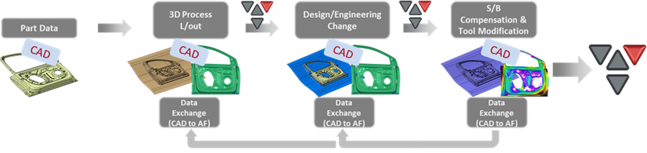
Fig. 1 Generalized representation of the existing workflow process
What defines each step in the existing workflow?
CAD software plays a central role in each phase of our current process. With this approach, the modeling results generated during the feasibility stage can be either directly applied or adjusted as needed for the final validation or CNC stage. If the initial attempt is successful and no design changes to the part are required, then starting with CAD-quality geometry could be the right course of action.
However, our work is never that simple. We have to consider numerous variables and boundary conditions, often requiring repeated design changes to the product. This complexity leads to multiple iterations of CAD modeling adjustments, consuming more time with every step. Moreover, the repeatedly modified CAD data needs to be transformed for forming analysis, resulting in additional time losses. Considering the practical constraints of having to complete engineering tasks for multiple products within a short period, in most cases, it’s not feasible to invest such extensive time and effort. As a result, the stage of development we’re in becomes a crucial factor in determining which tools we choose for practical implementation.
Can we enhance our current work process to cut down the time needed for each step? To answer this question, let’s take a closer look at the features of the AutoForm-DieDesigner product, which is crucial for advancing our engineering process. You can find more details in Figure 2 below.
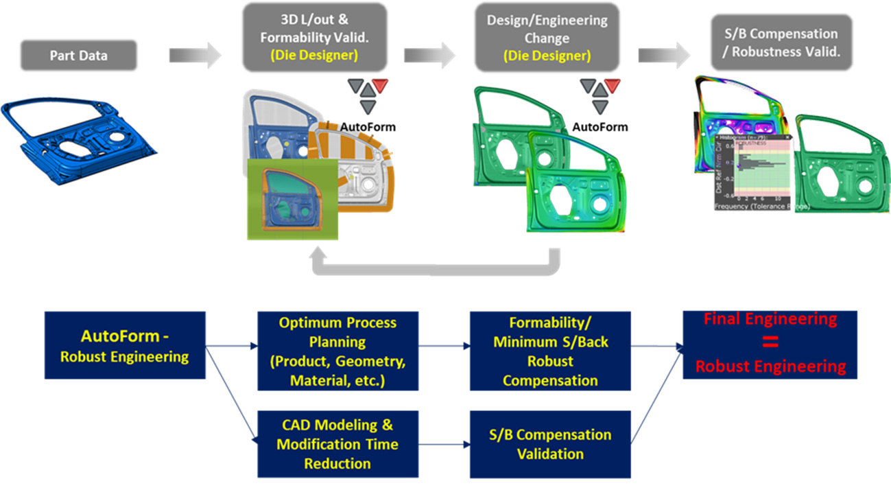
Fig. 2 Diagram of the improved work process using AutoForm and the DieDesigner features
When comparing our proposed improvement process to the existing work process, it’s evident that the two structures are quite similar. The key difference is that the work now starts with the AutoForm-DieDesigner product rather than traditional CAD software.
AutoForm-DieDesigner offers distinct advantages over conventional CAD software, most notably in its ability to significantly reduce the time needed for tool modeling and modifications. This is due to its unique flexibility and high-performance features. Moreover, it consistently delivers high-quality tool modeling results through ongoing updates. These results can be directly used for simulation and decision analysis, eliminating the need for data conversion and management, which is often required with CAD software.
The benefits of AutoForm-DieDesigner become especially apparent when handling frequent product design changes. With each round of modifications, the time savings add up. This accumulated time can then be reinvested in developing and evaluating a potentially more optimized process. By following this optimized process, we can improve quality metrics such as defect rates by ensuring formability or minimizing springback, as previously discussed. This, in turn, triggers a domino effect of reducing both time and financial costs in the field. Without exploring different processing variations, we might never discover a more optimized design.
Finally, let’s compare the characteristics of the existing and improved processes at each step, as illustrated in Figure 3 below.
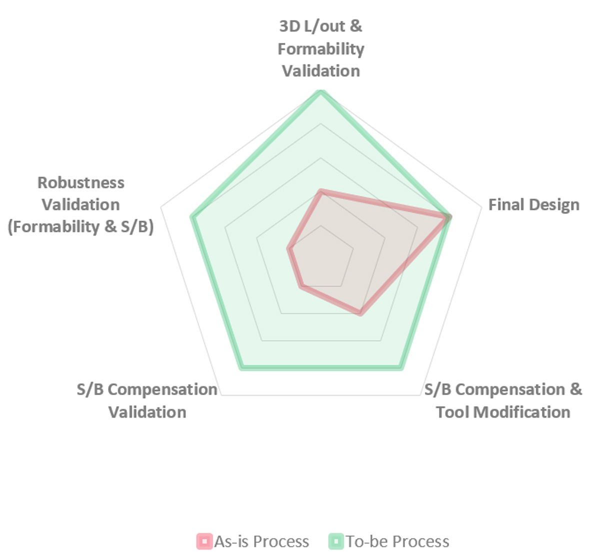
Fig. 3 Comparison of step-by-step characteristics between the existing process and the improvement process
In the current work process, all major tasks are carried out using CAD software. This means that time spent on modifying tool models due to design changes is a constant factor and adds up quickly. As a result, our limited time is entirely consumed by these modifications, leaving no room to directly lower the overall costs incurred throughout the work process by reviewing factors like “robustness” or “correction validity.”
In contrast, the improved process employs AutoForm-DieDesigner, which allows for quick and flexible adjustments to tool surfaces when design changes arise. This time-saving feature enables us to focus on reducing overall costs through a review of “robustness” and “correction validity.”
As you read this article, what are your thoughts—are you under the misconception that spending more time on a task equates to higher work efficiency? Or perhaps, amidst a hectic schedule and overwhelming workload, have you lost sight of what true efficiency means to you?
Of course, there might be some apprehension about adopting a new engineering process. Such a significant transition can be challenging without confidence in the proposed methods and tools. That’s why we aim to provide concrete evidence of the effectiveness and efficiency of the improved process in our article, Part 2.


?")


