
In this blog post we see how Volvo Cars includes tribological effects in stamping simulations with TriboForm. Special focus is given to the early tryout phase of dies in order to secure die tryout by solving as many problems as possible in forming simulations before proceeding to milling and casting. In the Volvo V60 car project, three parts were selected for in depth evaluation. Here are the results.
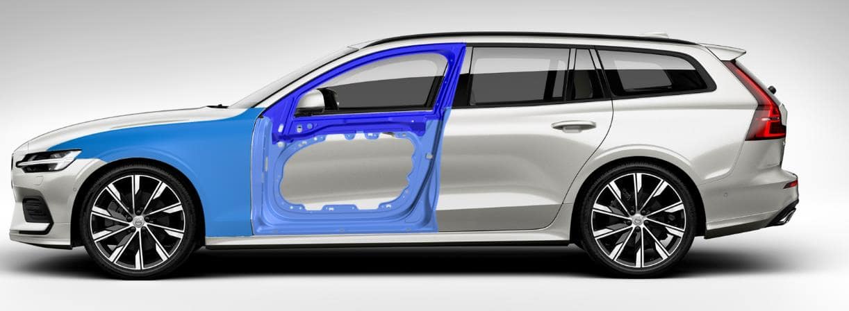
Figure 1. The new Volvo V60 and the parts included in the project.
At present the industry is facing several trends, particularly the increased use of aluminium materials and the increased use of thinner sheet materials. Marc Lambriks, General Manager at AutoForm Engineering Netherlands, joined us to tell us why. ‘The trends are geared towards lightweighting and they bring challenges including the fact that forming thinner sheet materials and aluminium is more dependent upon friction and tribology for the final quality of the part. Therefore, what we are seeing is a movement where tribology and friction is becoming even more important for accurately simulating the forming of those parts.’
To face this trend in forming simulations, Volvo Cars is collaborating with partners on this topic including the University of Twente, Tata Steel, TriboForm and AutoForm. Jan Harmen Wiebenga, Managing Director of TriboForm Engineering, explains: ‘The goal of utilizing TriboForm in Volvo car projects is twofold. First of all, the goal is to apply the TriboForm models on dies in early try-out. The motivation is that the majority of the forming simulations are performed to secure the die tryout, i.e. solve as many problems as possible in forming simulations before the final design of the die and milling of the casting. Secondly, the goal is to study the effects on stamping results of new lubricants and sheet metal coatings.’
In this blog post, the effect of friction and lubrication modelling in stamping simulations is demonstrated for the new Volvo V60 car model. The work includes in-depth evaluation of three different parts for the new Volvo V60, see Figure 1. The stamping dies for these parts are all manufactured at Volvo Cars tool shop in Olofström, Sweden.
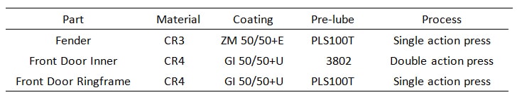
Table 1. Parts and materials included V60 car project.
Jan Harmen Wiebenga continued saying ‘Where quality of sheet metal parts is dependent on the friction conditions that occur during forming processes we must look deeper into the friction conditions themselves to extrapolate higher quality parts. Those conditions are further dependent upon the tribology system and all that entails; such as the interaction of the applied sheet material, coating, the tooling material itself, applied lubrication and process conditions.’ The parts and corresponding materials for the Volvo V60 car project are summarized in Table 1. Next, let’s look at a selection of the technical results.
The Door-Inner
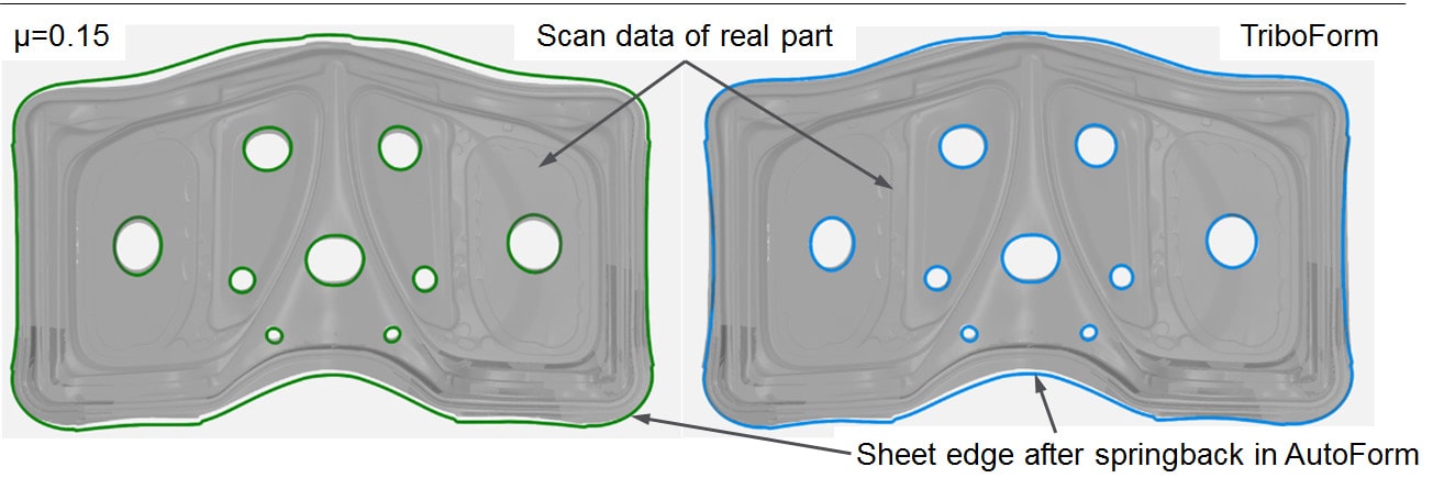
Figure 2: Draw in edge and pre-cut holes prediction of constant coefficient (left) vs. simulation using TriboForm (right). CLICK IMAGE TO ENLARGE
Jan Harmen Wiebenga explains: ‘In order to compare simulation vs. reality the part was taken off the press line and a 3D scan was made. The left hand image in Figure 2 demonstrates the scanned part vs. a simulation using a constant coefficient of friction of µ = 0.15. The grey area shows the real part, the green line shows the simulated draw-in prediction. You can see the problem here. The part has ended up with a larger draw in than the simulation predicted. However, on the right side is the TriboForm model in action. The blue line is now located much closer to the outer edge of the part. Even with a few imperfections still seen, the draw in was far better predicted. Now look at the improved prediction on the shape of the holes which are in the center of the part. The left hand simulation diverged greatly from the predicted shape. On the right side you see a nice match to the outlines. Therefore in addition to a better outer draw-in, within the product itself you see an improved prediction of the real flow of the material behavior in the dies.’
The Front Fender
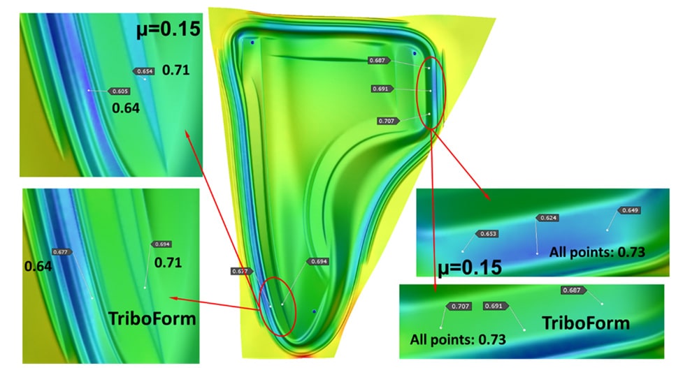
Figure 3: Thickness Measurements Front Fender. Top results show constant friction coefficient and bottom results are the TriboForm model. CLICK IMAGE TO ENLARGE
This time the thickness of the finished front fender part was measured on stamped parts and the results were again compared with the two simulations. Two areas were measured on the part. The top left result shows the constant coefficient of friction at work, which predicted a thickness of 0.605 and 0.654 (grey labels). In reality the part’s thickness came to 0.64 and 0.71. The bottom left image uses the TriboForm model and it predicted 0.677 and 0.694. Both of these are closer to reality. The same evidence occurs on the right side of the part. These results speak for themselves, i.e. the simulation results are closer to reality for the thickness prediction when using the TriboForm model.
To conclude, Marc Lambriks says; ‘OEMs have spent a great amount of time improving their material models, and software companies on improving the simulation codes they are developing. Naturally tribology is the next step and OEMs are now dedicating time in investigating better friction models. Especially in the case of Volvo Cars, they are progressing to a point where they are satisfied with both the simulations and advanced material models they are using. They, like most OEMs, are looking for the next step to improve their simulation accuracy and reduce tryout corrections. This is why they are investing time in TriboForm as friction modeling is the next step forward.’
New readers, sign up to this blog to get more. Once a month we’ll send out just one email with our latest top blog posts. Thanks!


?")


