
Introduction
Did you know that manual shimming processes are outdated? Modern OEMs now rely on virtual shimming. This methodology significantly reduces lead time and manual efforts, which can result in six-figure euro savings!
Tolerance issues are common and almost inevitable in BiW assembly. Building an assembly is hardly straightforward, and even when stamping parts are within tolerance, an assembly may not be. Therefore, when you are in a ramp-up to production phase, the objective is to bring the assembly within tolerance. If that’s not the case, then two questions arise:
- What can be solved in the body shop?
- What needs to be solved in the tool shop?
Focusing on the body shop, two typical actions can be triggered. One is to work on the shimming of clamps, which is probably the cheapest approach. The second is to adjust the joining sequence, a more expensive process-side change. In this article, we share exclusive insights into the potential of virtual shimming and teaching optimization that we have investigated globally in collaboration with customers, leveraging AutoForm Assembly and its dedicated module BuildOptimizer.
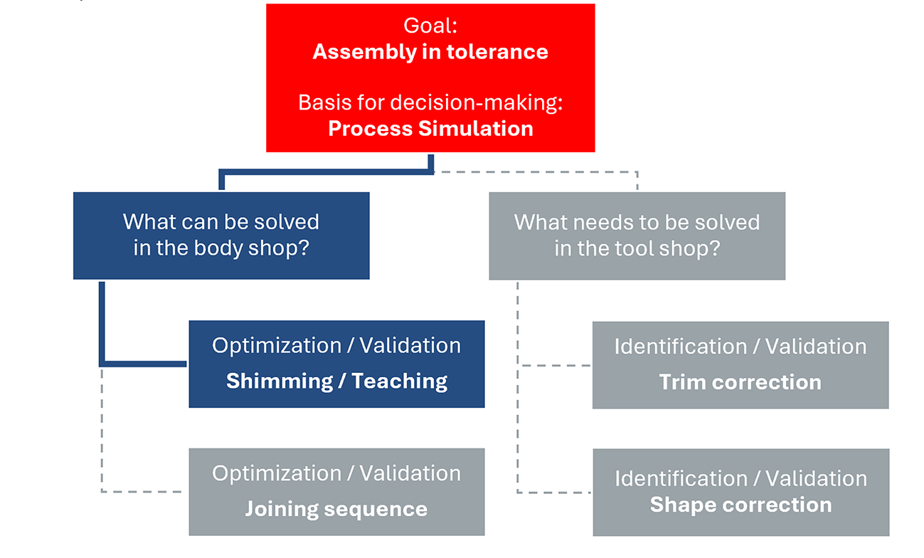
Figure 1: Counter measures in the body shop and tool shop in case of tolerance issues in BiW assemblies
The main potential savings are:
- Reduction of “BiW-triggered” quality loops or countermeasures in the tool shop
- Reduction of the amount of tryout or procurement of pre-series assemblies
Shimming Process
On the assembly unit, a common approach is to shim part fixation points to compensate for deviations caused by the joining process. This involves modifying the position of the clamps. Thin plates of metal (known as “shims”) are placed either on the upper or lower clamp. Typical shim thickness ranges from 0.1 mm to 2 mm, and multiple shims can be combined to achieve the desired result. The goal is to locally overbend and tighten the parts against each other so that the assembly is within tolerance after joining and when the clamps are opened.
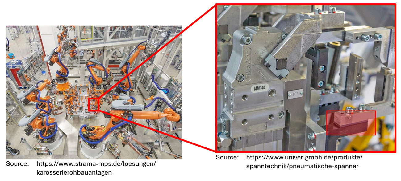
Figure 2: Shimming process
Within the software, the user can modify clamp (and join) settings and perform a virtual shimming optimization. The principle is as follows:
- Select the clamps to be shimmed and define:
- Specific shimming values manually (e.g., -0.5 mm)
- A possible shimming range (e.g., ±2 mm) for different clamps to perform an automatic optimization
- Allow for a position correction of welding guns by activating the teaching option
This methodology can be applied to several clamps (or joins) across different operations, with the goal of achieving optimal dimensional accuracy without time-consuming and costly trial and error. This approach is revolutionary because it is currently considered almost inconceivable in the body shop to correct multiple areas in a single loop, due to unpredictable interdependencies. Therefore, this methodology can dramatically reduce the number of shimming validation loops.
Door Assembly Example in AutoForm
Let’s look at an example. Here, we consider a left-hand side door inner subassembly consisting of an inner part, various reinforcements, and a side impact beam. Different materials are used, such as low- and medium-strength steels as well as press-hardened steels, varying in thickness from 0.7 to 1.5 mm.
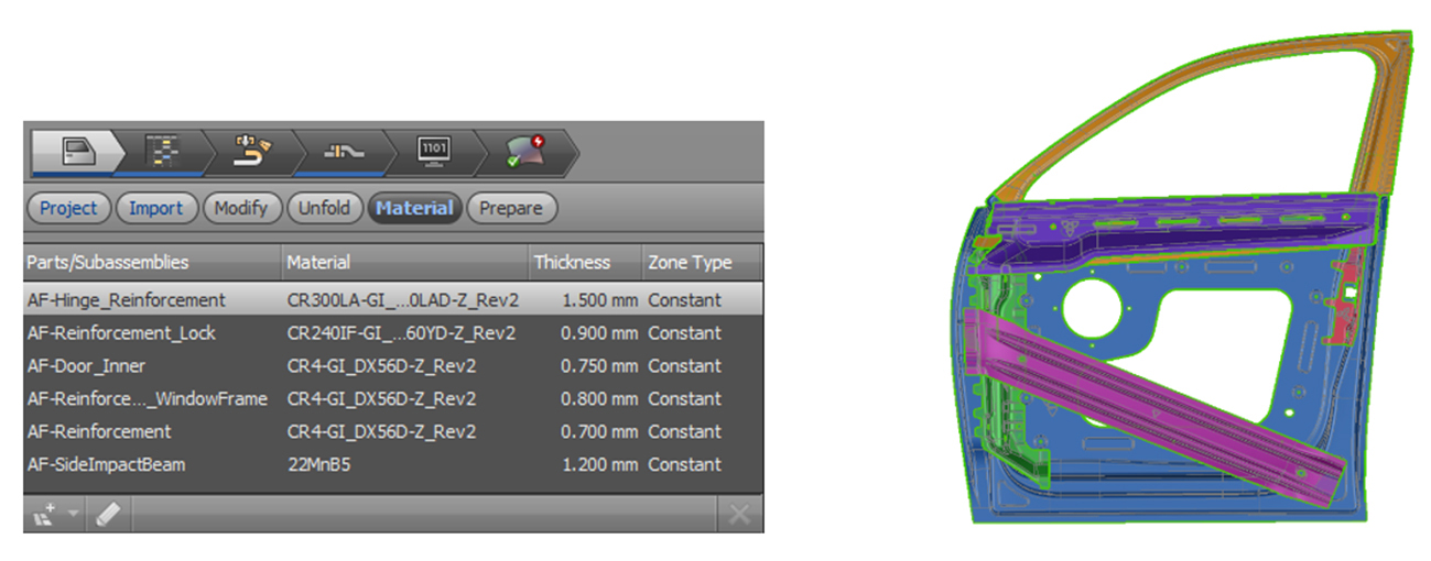
Figure 3: Door inner subassembly
The parts are assembled in three main operations by joining them with resistance spot welds. First, the door inner part is joined with the hinge and lock reinforcements (A-10). In the second operation, an additional reinforcement is assembled (A-20). Finally, the subassembly is joined with the window frame reinforcement and the side impact beam (A-30).
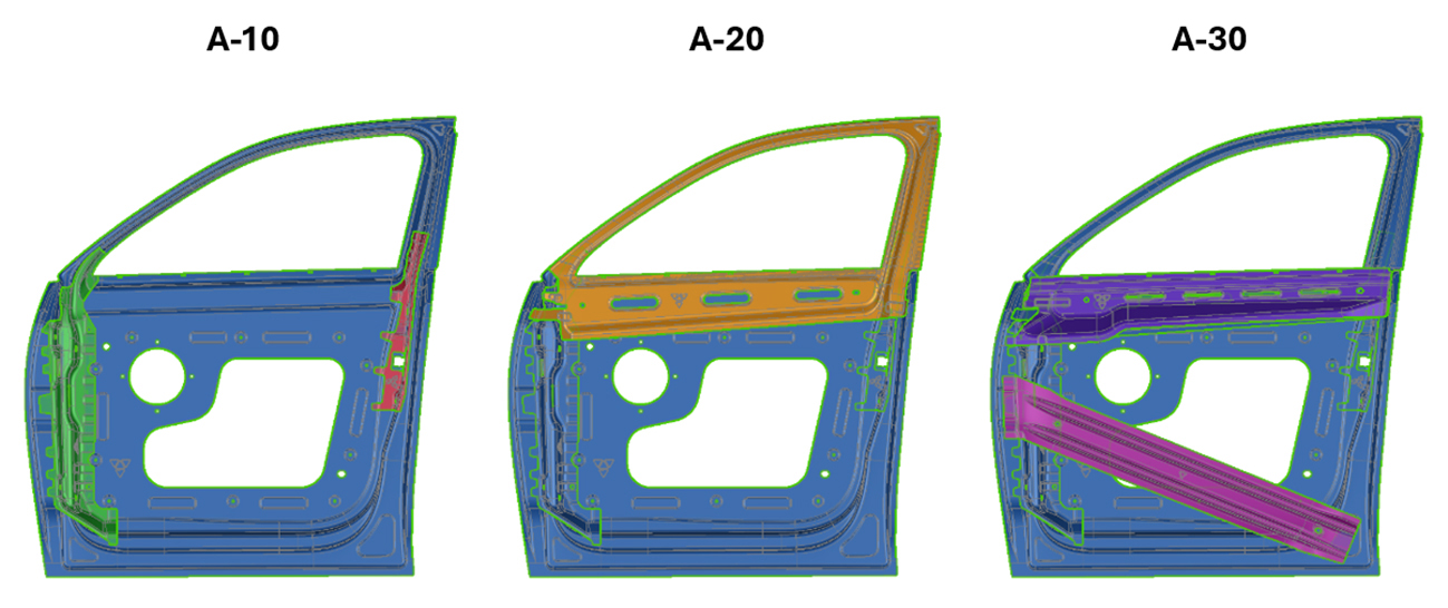
Figure 4: Assembly process
The software allows the user to define simulation input based on the results of the single-part forming simulations. In this way, dimensional deviations, stresses, strains, and thicknesses from the forming process—factors that significantly impact the final BiW assembly quality—are integrated into the assembly simulation. Prior to the joining processes, the parts were compensated until they were within tolerance. But the question is:
- Do green (in-tolerance) single parts lead to an in-tolerance assembly?
Looking at the assembly simulation results, even though all single parts have been compensated within tolerance, large dimensional deviations remain in the final assembly, exceeding ±1.5 mm. Strains and distortions resulting from the joining processes lead to an out-of-tolerance assembly, so the optimization process in the body shop begins.
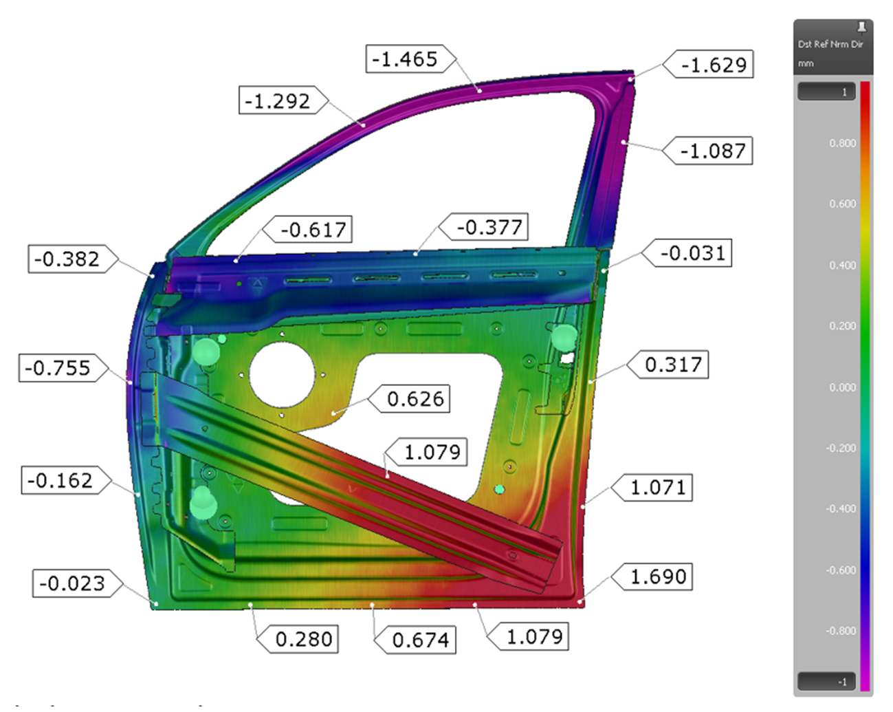
Figure 5: Deviations resulting from the assembly process
Manual vs. Automatic Shimming
First, one can use the software to improve dimensional accuracy by applying manual shimming. This means user-defined setup for shimming and teaching, plus manual evaluation of trial-and-error simulation loops.
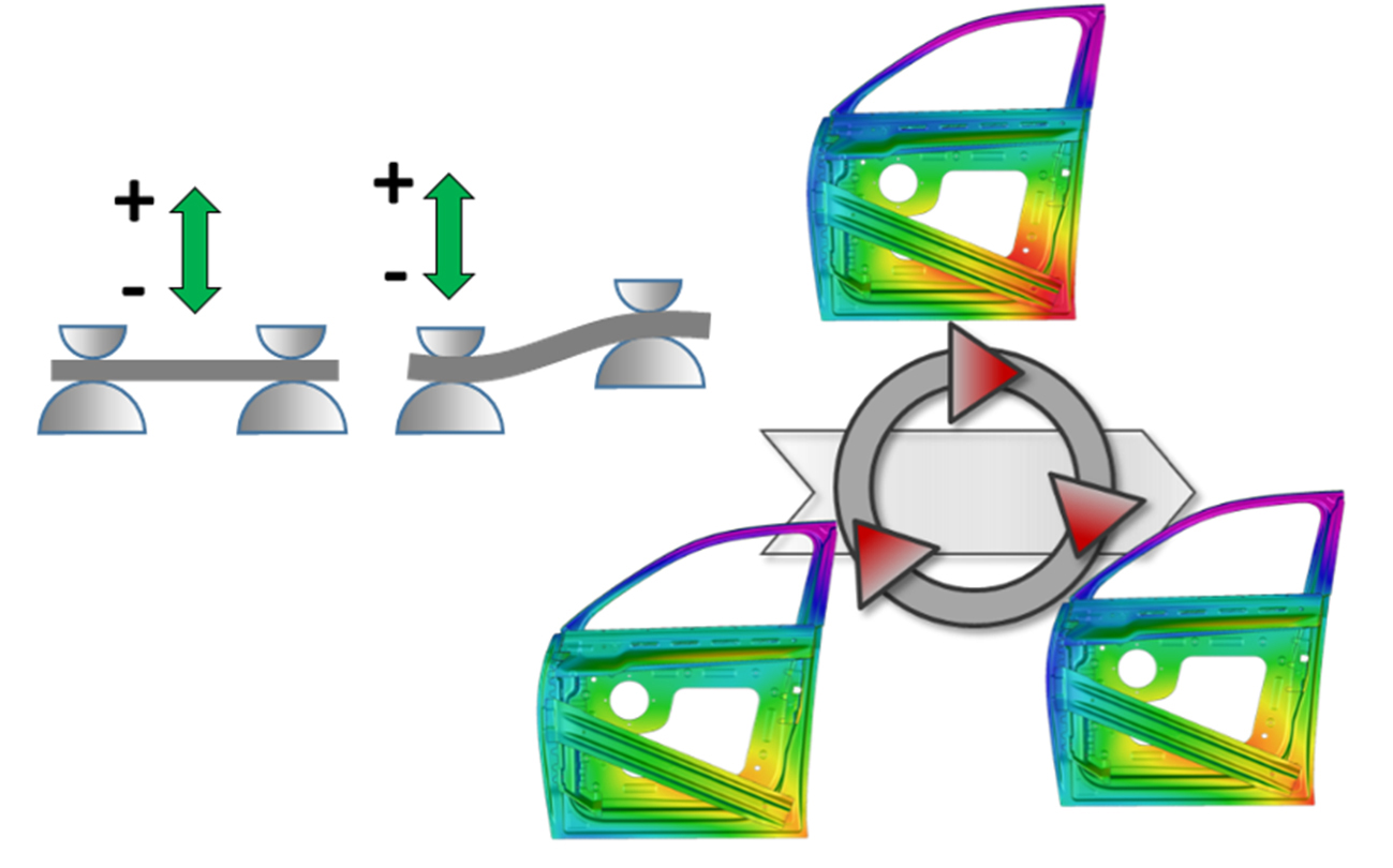
Figure 6: Virtual shimming through a manual approach
However, this option is highly dependent on the user’s expertise and can be time consuming, as dependencies are often non-linear and multiple trial-and-error loops might be required.
A more efficient second option relies on an automatic optimization within the software. Here, the user can define shimming ranges for different clamps, and the software automatically calculates a range of possibilities. This triggers an automated tolerance-based optimization across different assembly stations. The user can then easily perform a sensitivity analysis of individual clamping points and derive process windows in a very short time.
In our door assembly example, a specific shimming and teaching setup was defined for operations A-10 and A-30, and the simulation was executed. After defining tolerance limits and starting the automated optimization, the software provided suitable process windows within seconds to produce assemblies in tolerance.
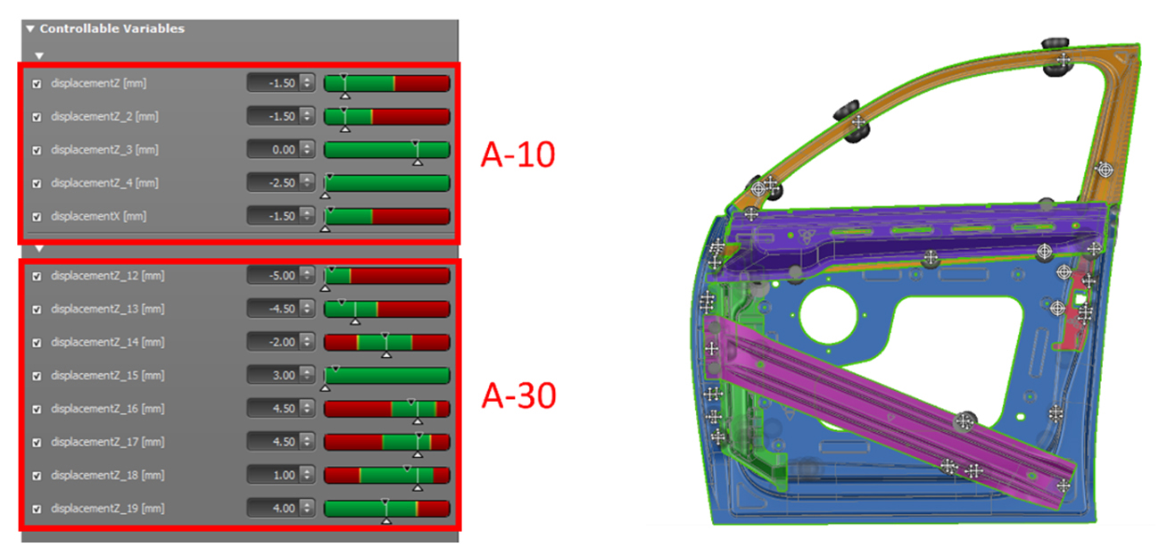
Figure 7: Virtual shimming through the automatic optimization approach
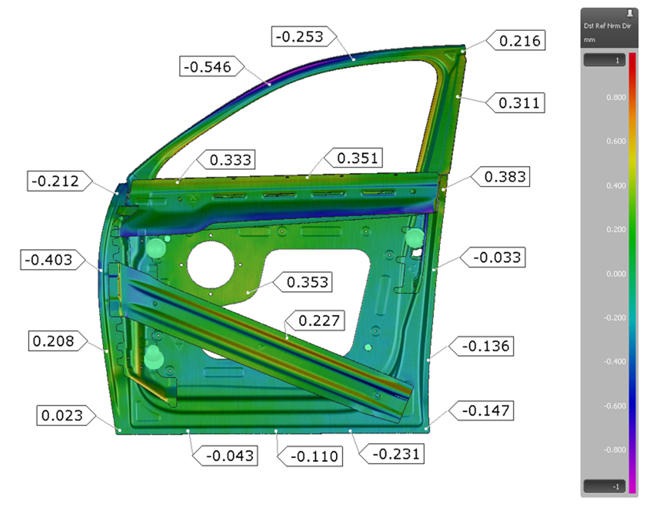
Figure 8: Deviations resulting from the optimized assembly process using virtual shimming
Keep in mind that shimming may not be the only solution. In the worst case, it may be impossible to resolve certain issues by shimming and teaching (for instance, because shimming values are too large). In this case, other countermeasures must be taken, such as adjusting the joining sequence or making assembly-based modifications in the tool shop.
More Efficiency with Virtual Shimming
Figure 9 shows the typical way shimming occurs in a standard organization. All modifications are made iteratively, with expert-led actions for both defining shimming parameters and implementing them. Multiple iteration loops are often required, which can take days or even weeks, depending on complexity.
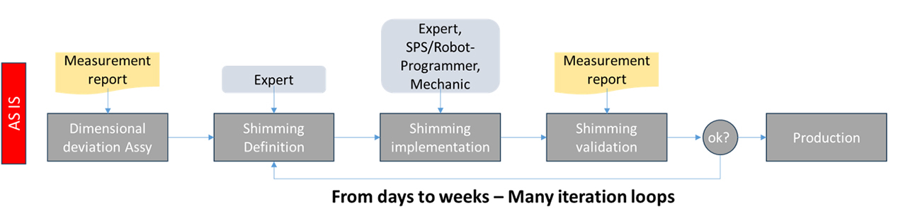
Figure 9: AS IS state of the shimming process in the body shop
Now, we have demonstrated that Virtual Shimming is an effective way to quickly determine the right shimming settings to achieve an in-tolerance assembly. By combining Virtual Validation with the shimming definition suggested by your expert, you can run multiple virtual trials before applying the shimming on the line.
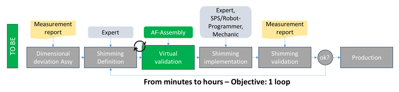
Figure 10: TO BE state of the shimming process in the body shop
So, while shims themselves are cheap, significant savings are realized in the lead time spent finding the correct settings and implementing them. Ultimately, the goal is to go from days (or weeks) to hours, with a single iteration loop.
Changing an organization’s internal processes can take a long time, considering persuasion, software testing and validation, process development or redesign, and rollout. Our experience shows that it is crucial to start process changes as soon as possible because software development progresses faster than implementation on the customer side.
Conclusion
In summary, virtual shimming provides unique benefits, especially at tryout and production support:
- It reveals the influence of individual clamps and enables optimization across different assembly stations.
- The software is more than just another simulation tool. With “Virtual Shimming,” you gain a key solution for process decision-making.
- The “Automatic Shimming” capability is truly unique. Users can quickly see the impact of variations on a selection of clamps and identify a “Green Process Window.” In just a few seconds, you get results that would normally take days!
- All of this complements and extends the knowledge of geometry and quality experts. It also reduces the effort spent on Q-loops, pre-production builds, and the procurement of pre-series assemblies.
Testimonial from Linde + Wiemann SE & Co KG
Mr. Christian Beschnorner (Dipl.-Ing., Stamping Technology, FEA/Process-Engineering) is a long-standing AutoForm solutions user. He highlights the benefits of the methodologies discussed above for improving BiW engineering and reducing costs related to pre-production at pilot hall:
“When you use AutoForm Assembly, you gain detailed insights into your processes and increase your process understanding to accelerate the availability of your production lines and shorten your test runs. I have been gaining experience for 5 years with this new approach to process engineering for the entire BiW process chain, including stamping and assembly.
Regarding Virtual Shimming, the prediction really works. I have had experience with different spot and line welding projects over the last few years and have learned a lot about the entire process chain of BiW do’s and don’ts. We stay calm, remain one step ahead, and look closely at how we can redefine our approach to process understanding and find new ways for improvement.”


")


?")


