
Small Sized Tool Shops Embracing Digital Engineering Tools
The automotive tooling and part stamping market has become increasingly competitive, favoring companies that embrace both change and relevant advances in technology. One of the most helpful digital tools being employed is simulation, which offers great potential gains in terms of time, assertiveness, confidence and process control.
Empirical knowledge is still widely considered the gold standard in the Brazilian industrial environment. However, simulation has shown that a cultural change is necessary to obtain agile and assertive results. Large companies are realizing that their greatest advances will be obtained through the small details, which only specific tools can present.
In this article, we will detail the critical benefits of sheet metal forming simulation software as carried out at the Vtron Serviços LTDA projects office. We will also discuss the accuracy of the results in a case study.
Vtron Serviços LTDA was founded on February 14, 2014 in Joinville, Santa Catarina, Brazil by Alessandro A. de Moura and his son, Allan A. de Moura. They steered their new company in the direction of tool design for stamped products. With over 30 years of combined experience in sheet metal parts, they provide superior solutions in process design, simulation and die tool design for both inner and outer vehicle panels. They support tool shops in all of Brazil and abroad and work directly with vehicle manufacturers on feasibility solutions.
With increasing OEM customer requests, they recognized the need to implement AutoForm solutions into their engineering processes at the beginning of 2017 in order to maintain their market position. One of the requests they received was better sheet control for each operation, which would allow for a shorter tryout time, thus improving profitability. Naturally, this required both simulation and process control.
Vtron’s decision to incorporate AutoForm caught the attention of a few small and medium sized tool shops, who believed they were far from having access to this technology. It has widely been assumed that only large companies have the necessary capital to invest in software solutions. However, these smaller tool shops had not evaluated the returns they could gain through significant reduction in tryout time, blank and cut line optimizations and better dimensional control of the final product.
After the initial skepticism that usually accompanies big changes in this market, and following the successful results obtained in different projects, Vtron received wide acceptance in the market as a project company.
Following, we will detail Vtron’s turnaround project as an illustration of the gains they have achieved by implementing AutoForm. In the project, the drawing tool was complete (tryout finished) and it was time to move on to the tryout of the trim operation tool. As shown in Figure 1, the position of the drawn panel on the trimming tool, which was milled according to the nominal geometry, was incorrect because of the springback of the panel itself.
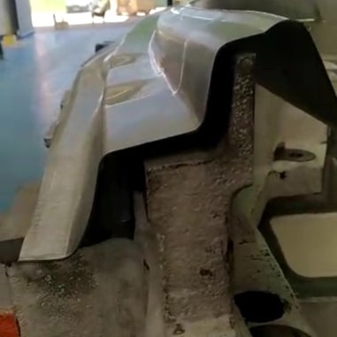
Fig. 1: Trim tool fitting failure after pullout
Figure 2 shows that the results of the process simulation predicted the exact behavior of the panel and the scenario that was occurring in tryout.
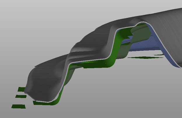
Fig. 2: Trimming tool fitting failure in the simulation
With the goal of obtaining a good fit of the panel on the trimming tool, the drawshell compensation of the tool was performed in simulation. Drawshell compensation interprets the result obtained from the simulation of the drawing operation after the springback of the panel and through a vector field. It then deforms the nominal shape of the cutting tools so the panel will fit on it correctly, avoiding any possible restrike of the pad and post of the tools.
After evaluating different solutions of the compensated tool surfaces, and once the theoretical result obtained in the simulation was satisfactory (i.e. an acceptable fit of the product in the cutting operation was achieved, thus eliminating the risks of additional unwanted plastic deformation of the sheet), the tool was re-milled. Figure 3 shows the digital prediction of the sheet’s position on the trimming pad.
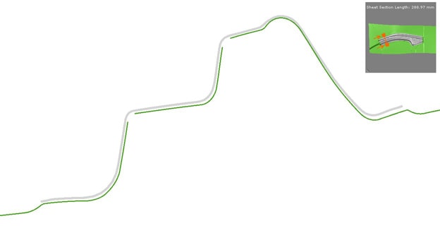
Fig. 3: Fitting after drawshell
The surfaces of the tool used for simulation were suitable for machining as well, so there was no need to regenerate the surfaces in CAD.
The tool was milled accordingly and the solution described by the software was better fitting, as shown in Figure 4. This ensured better process dimensional control coming from the draw operation itself, as subsequent operations will not deform the product due to the pad closing.
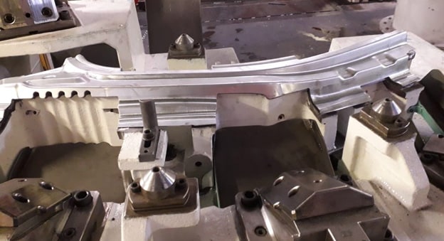
Fig. 4: Product based on the cutting tool after compensation made in simulation
In addition to ensuring fitting in cutting operations, the simulation can also demonstrate its robustness with respect to theoretical results that are linked to the mechanical properties of the stamped sheet. These properties are responsible for providing the most important information regarding the feasibility of the process, in addition to its influence in the springback that occurs after each operation.
With all of this available information, it is possible to predict compensation strategies that can considerably reduce tryout time, offering tool shops new resources and competitiveness in relation to tool construction time. The strategy begins with understanding where the springback comes from. From there, compensation will bring the product within the tolerances required by the automakers.
Another method for improving the accuracy of the results is through characterization of the material properties in the software. The small variations that exist when the material is produced at the steelmaker can considerably influence the practical results, creating minor differences between simulation and practice. One of the solutions to reduce this noise is evaluation of the process stability. Calculations taking into account the variations that can occur in material lamination help to create a more robust process for compensation and production of the product.
Figure 5. below shows a geometry modification performed with approximately 12mm of torsion for compensation. After the first stroke and without too many adjustments, the resulting part fell within the tolerance of ±1.5mm of the final product. From this step on, further adjustments were made with the understanding of the factors that may have influenced this discrepancy between the virtual calculation and reality.
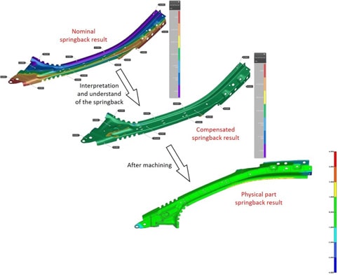
Fig. 5: Theoretical and practical result of product compensation
To ensure speedy development of the whole process, besides efficient and robust software, there must also be excellent communication between the engineer responsible for the simulation and the team in charge of the tooling design and construction. In this case, JM Ferramentaria, in Minas Gerais state, provided Vtron with all the necessary information regarding the product and tools, so that both teams could focus on solving the problems in question. Engineering and tooling should work together to guarantee the best products with fair deadlines.
(Left) Allan Alencar de Moura (Right) Wesley Aparecido da Silva
Allan Alencar de Moura – Technical Director of Projects and Simulation at Vtron Serviços – Engineer responsible for the validation of processes, simulation strategies and design concepts of stamped items tools, with more than 10 years of experience in the area of sheet metal forming. +55 47 30292027 / allan@vtron.com.br
Wesley Aparecido da Silva – Application Engineer at AutoForm Brazil – Supports customers, backed by over 9 years of experience in stamping, specifically in the areas of Stamping, Quality, Process Engineering and Tooling. +55 11 4121 1644 / wesley.aparecido@autoform.com.br


?")


