From Blank Size Development to Final Material Cost – Were Your Projections Right?
In the sheet metal forming industry, material generates one of the largest recurring costs in the manufacturing process. Reducing waste is paramount to controlling production costs and increasing profitability. Eliminating 5mm of length from a 1500mm wide, 1mm thick aluminum blank can save $0.05. Not important? For a 600,000 part production it saves over $30,000 in material cost. Achieve similar results for only 4 more parts, and you have saved over $150,000.
Accurately predicting blank size is critical in the quoting process as well. If the blank size is underestimated, an increase in size may yield reduced profitability for a given project. On the other hand, overestimation of blank size can result in a project being awarded to a competitor and loss of company revenue. All of this must consider a realistic forming process and its resulting part formability.
AutoForm-StampingAdviserplus allows tooling professionals to more accurately predict blank size, and optimize layout within a coil. It enables users to understand material usage by comparing blank size versus the final part to calculate yield percentage. This can be done from early in the planning stages, and can be further optimized using AutoForm-ProcessPlannerplus and AutoForm-ProcessExplorerplus to define the process and validate through simulation, ensuring maximum benefit is achieved.
Historically, developing blank size estimates early in the product development process can be less accurate, as less information is known about the manufacturing approach:
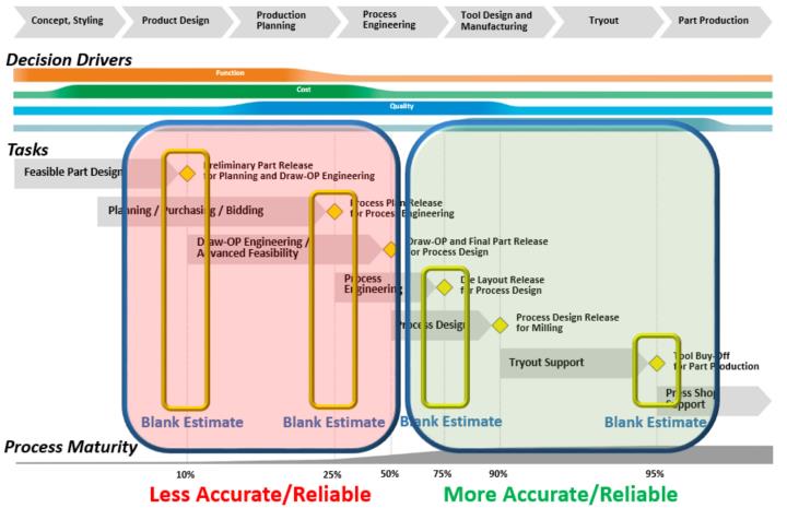
Fig 1: Product Development Cycle with Blank Estimate Timing and Accuracy
Additionally, there is a tendency to focus on only blank size in an effort to minimize material cost and drive down piece cost. However, material costs cannot be determined in a vacuum.
Material costs are only one potential decision driver among the many factors that determine the success of our products.
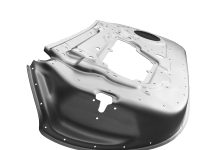
In AutoForm-StampingAdviserplus, users can take advantage of the Formcheck to begin blank development. In its base functionality, the user must choose ‘Draw Parts’ (assuming this is a draw operation) and must apply the ‘Develop Part’ requirement within. By doing this, the result is a minimum material requirement obtained by simply unfolding the part geometry. Here is an example with a Door Hinge Reinforcement:
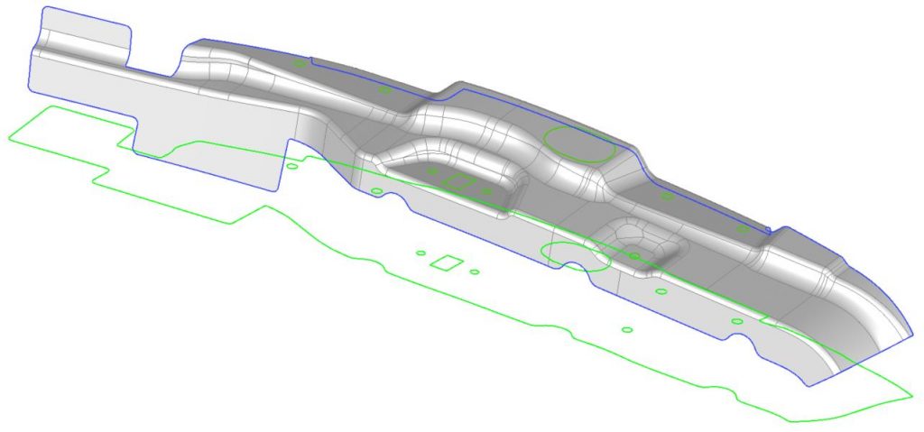
Fig 2: Part with Minimum Material Requirement developed by Flattening of Part
This can then be embedded into a blank and coil configuration, yielding an initial blank shape for the draw process. However, if at this point the user believes this blank to be accurate without considering other factors, the result could be a blank that is too small for production. This could win a bid for a project, but could yield catastrophic cost impact later when the blank needs to be increased for tooling needs.

Fig 3: Minimum Material Requirement Embedded into Blank from Coil
To prevent underestimating a blank for a draw process, users can develop ‘Draw Geometry’ within the same Formcheck in Stamping Advisor. Keep in mind that this is not used for the incremental simulation, but is solely developed in the Formcheck to understand potential forming concerns and develop better blank estimates. To create this geometry, you must move to the ‘Draw Geometry’ tab and select the items for AutoForm to generate. There are options to create a Boundary Fill (smooths perimeter of the part), Double Fill (when simulating 2-out or double-attached parts), Wrap Surface (Formcheck’s representation of a binder surface) and Addendum. All of these items allow the user some range of adjustability.
Additionally, users can choose to define Secondary Forming areas to eliminate geometry from Draw consideration. An example of Secondary Forming would be a flange that is to be developed in the draw, and formed in a later operation.
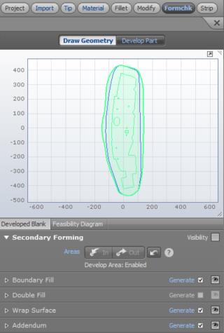
Fig 4: Development Options for Draw Geometry
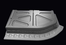
Returning to the Hinge Reinforcement example, we have chosen to add flanges to the Secondary Forming. Additionally, we have created Boundary Fill, Wrap Surface and Addendum geometries. No changes have been made to the result, and the dashed trim line shows that some areas will need to be trimmed by cam. The resulting geometry now begins to at least consider a more realistic manufacturing condition:
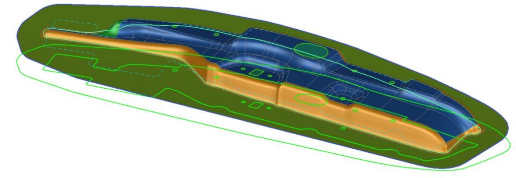
Fig 5: Developed Draw Geometry with Minimum Material Requirement
The change to the blank result is also considerable, yielding a much larger blank as compared to the basic unfolding of the part:
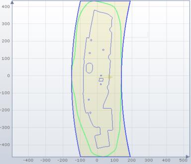
Fig 6: Minimum Material Requirement Embedded into Blank from Coil
At this point, the user needs to begin to understand more about production intent, and discussions with tooling design can be helpful to gain more insight. By considering possibilities like double attached parts, improved flange development and other factors, more can be done to improve initial blank estimates within AutoForm-StampingAdviserplus.
Building upon the earlier Hinge Reinforcement, it was decided that double attached parts were feasible and that it would be best to eliminate cams for cutting purposes. By returning to the Import page and defining a symmetry plane, the user can then redevelop the Draw Geometry of the Formcheck. It does not have to be exact, as the details can be resolved during the tooling design phase; however, this application begins to align much more closely with manufacturing intent, and the resulting blank is a much more reasonable estimation occurring very early in the product development cycle:
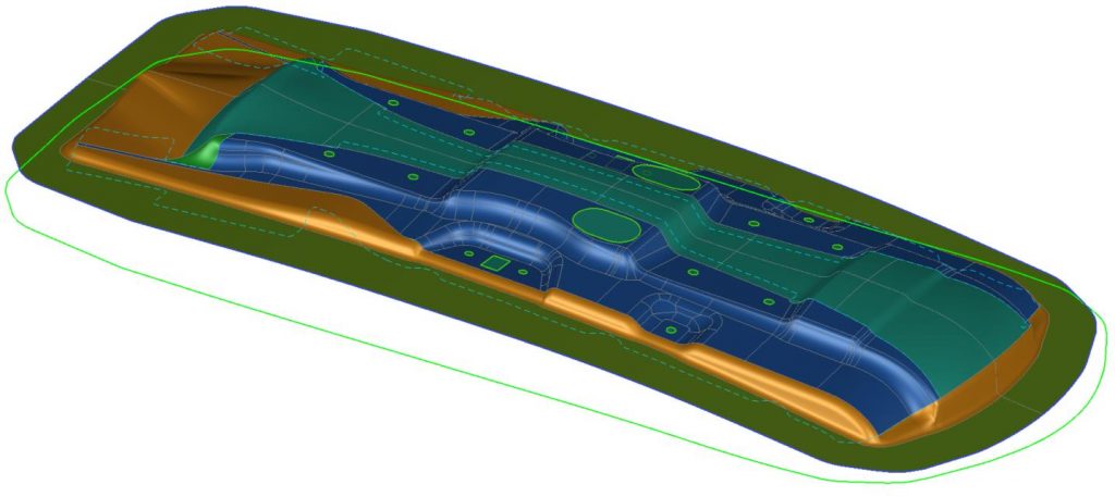
Fig 7: Improved 2-Out Developed Draw Geometry with Minimum Material Requirement
Progressing through these steps allows the user to refine the blank with confidence, and mitigate risk of large changes at production. In our example, the first unfolded blank was too small, but would have only cost $1.22 per part. It’s a low cost result, but unrealistic for tooling (unless crash forming, where no trim is required). Once we added addendum to the single part, the blank grew considerably, and would have cost $2.85 per part. This estimate may prevent winning a job by being too high.
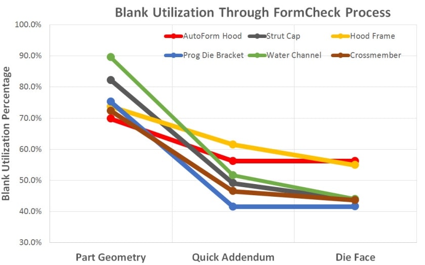
Figure 8: Three blank estimation methods are shown and
results for each with different part types.
With very little additional time, a more accurate assessment of the blank size and formability can be completed. The Quick Addendum method also shown in Fig.8. By taking time to learn more about production intent and moving to a double attached part, the blank came down to $1.99 per part. By comparison, the final engineered solution (double attached) for this part is a blank costing $1.84 per part. This means that the final estimate obtained from the AutoForm-StampingAdviserplus approach was within 8% of the final production blank. This is a much more reasonable starting position for a project, and should allow users to estimate blanks with confidence.
Thank you Todd for this insightful post. For new readers don’t forget to subscribe to our blog to stay updated. We’ll never send you any marketing emails. You’ll get just one email per month on the top must-read posts, so you can stay informed on the industry’s latest.


