Influence of lubrication amount, tool roughness and sheet coating on product quality
[dropcap]T[/dropcap]riboForm has been a hot item in the world of social media. Here we continue this series covering their experience on controlling friction for achieving high quality parts.
The quality of a part is strongly dependent upon friction and lubrication (tribological) conditions which in turn may cause forming operations to succeed or fail. Here, choosing the optimal tribology system at an early stage of the design process enables engineers to avoid wrinkles, splits and other issues in production.
In this case study TriboForm examined the influence of 1) lubrication amount, 2) tool roughness, and 3) sheet coating type on the occurrence of fractures and wrinkles for a front fender product. During the examination the TriboForm software was used in combination with the AutoForm software. The front fender used for the investigation was 2002 Numisheet benchmark fender, offering a well-known candidate.

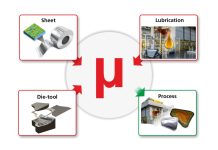
Figure 1. Approach for friction and lubrication modelling
in sheet metal forming simulations.
The beauty of the friction analysis model used by TriboForm is that not only does it generate a tribological system, but it further exports this as a ‘friction file,’ which is then used in forming simulations run using the AutoForm software. In other words – the tribological system incorporates the applied sheet material, coating, tooling material, lubrication type/ lubrication amount and process conditions, which may now be run in simulation.
Looking deeper into the friction file we learn that the TriboForm software calculates ‘friction coefficients’ for a predefined range of process settings, such as local contact pressures, relative sliding velocities, plastic strains in the sheet itself and interface temperatures.
Bringing this data into simulation through the friction file is done through the TriboForm FEM Plugin, which is integrated in AutoForm R7. This means that if an AutoForm simulation is started the FEM Plug-In reads the friction file as exported from TriboForm and enables the usage of the friction model within the AutoForm simulation. Thus, the generic constant coefficient of friction in AutoForm is replaced by the advanced friction model taking into account the specific conditions of the tribological system in every single spot of the sheet/part.
The Front Fender and Tribology in Practice
Made from a coated mild strength steel sheet (DX54D), the material was lubricated with standard drawing oil, with the process conditions of the 2002 Numisheet benchmark. Two lubrication amounts of 0.6 g/m2 and 2.0 g/m2 were analyzed during the test in order to show the influence that lubrication amount itself has on final part quality.

Figure 2. Impression lubrication amount on the sheet surface. Left: 0.6 g/m2. Right: 2.0 g/m2, whereby the blue transparent plane indicates the lubrication level.
Then the TriboForm software was used to simulated friction conditions by loading and sliding the tool surface onto the sheet surface, examining the effects of predefined contact pressures, strains, sliding velocities and temperatures to generate the result.

Figure 3. Max failure (left), Friction distribution (middle)
and Forming Limit Diagram (right)
Amongst several detailed results, it was shown that the decrease in friction coefficients positively influenced the formability of the part as can be seen from the corresponding Forming Limit Diagram. However, as strains were within 10% distance from the Forming Limit Curve, the part was judged as critical. By reducing the roughness of the tooling from 0.4 µm to 0.2 µm, resulted in a decrease in friction coefficients for the complete part, see Figure 5 (middle). The reduction in friction coefficients then resulted in a ‘safe part’ without any risk of splits, although potential areas for wrinkling were observed in the blankholder area due to the occurrence of compressive stresses. From Figure 5 (right) it could be observed that changing the sheet coating from electrogalvanized (tribology system 1) to hot dip galvanized (tribology system 4) would also result in a general decrease in friction coefficients. A safe part was then predicted with a lower risk for wrinkles compared to tribology system 3 (reduced tool roughness), as more stretch was introduced due to the occurrence of higher friction coefficients.

Figure 4. Distribution friction coefficients and corresponding FLD for a lubrication amount of 2.0g/m2 (left), Fine polished tool surface (middle) and Hot dip galvanized coating (right)
Conclusion of the Case Study
The original study was clear; a strong influence of tribology, friction and lubrication was seen on both the part quality and overall production stability. More importantly, it was demonstrated that the initial critical product could be improved to a safe product by adjusting and optimizing the tribological conditions.
That is to say, it was proven that tool roughness and type of sheet coating significantly influences final part quality. It is demonstrated therefore that realistic and accurate friction and lubrication conditions improves the predicting capabilities of stamping simulations, bringing metal forming simulations to a higher level in both qualitatively and quantitatively predictions.

Figure 5: Simulation set-up front fender in AutoForm (left) and final formed product (right)
Thank you for visiting our site again dear readers. If you subscribe to our blog you’ll get our sheet metal technology blog post updates to your inbox.
* Original white paper by: Johan Hol TriboForm, Jan Harmen Wiebenga TriboForm, and Bart Carleer AutoForm.


