For the continued growth of tube-hydroforming, better methods for creating and validating springback compensation are essential. Upcoming vehicle programs forecast increasing use of Advanced High-Strength Steel along with more tube-hydroformed parts. The release of AutoForm-HydroDesigner2016 represents the first commercial solution specifically for compensating closed-section geometries processed using tube-hydroforming processes—NC tube bending, preform, and hydroforming.

First, it is necessary to recognize springback at the various stages of the process, from tube to finished product. Initial planning typically begins with a pre-bent tube, which is loaded into the hydroforming die. AutoForm-HydroDesigner2016 automatically finds the centerline of the closed-section part and the tube fill addendum, and then proposes a bend schedule based on user inputs such as size(s) bending disk(s), number of bends allowed, and original tube diameter.

initial tube bending is based on centerline of the net shape part, but springback after bending can translate the tube away from planned centerline
After bending, springback shifts the tube centerline away from the intended net shape of the part, possibly even preventing the loading of deformed tube into the following operations. Manually defining the centerline of a part without compensation is already difficult; applying springback compensation to the centerline is not any easier. Using software to correct the centerline to account for springback builds a new bending schedule that addresses springback effects.

Springback compensation builds a new bending schedule to compensate for the springback observed; after springback the compensated part is closer to the net shape intent
With the tube starting the hydroforming process closer to the planned net shape of the part, any further springback-induced translation of the tube, twist, or crowning specific to hydroforming deformation can be addressed. Without compensation software, engineers and toolmakers would have to make educated guesses of how to adjust the tooling geometry to correct for the springback. In CAD, new tooling geometry would need to be built or existing data morphed. New geometry would then either be cut as prototype/proof tooling or further evaluated using finite element analysis (FEA) software.

Case Study: DP1000 Roof Rail, Ford Lincoln MKZ 2016

2016 Lincoln MKZ and view of similar vehicle showing position of the roof rail (source: Great Design in Steel 2015)
Schuler Group recently put this approach into practice with the engineering of the roof rail for the 2016 model year Lincoln MKZ. What follows are the results of the engineering study.

Forming process and part geometry of the Lincoln MKZ 2016 roof rail
The selected material (Dual Phase 1000) is difficult to form with a conventional (high-pressure) hydroforming process; instead, a pressure-sequence hydroforming process is selected. The process starts with seven bending steps and a preforming operation, followed by hydroforming. At the beginning of hydroforming, lower pressures are applied during closing of the tools. After closing the dies, pressure increases for a final expansion/calibration of the part shape.

Springback results considering all forming operations

Springback after bending to planned net shape (grey), tube after springback (red) will not fit the tool (yellow)
Initially, springback after the bending operation is analyzed the predicted springback at the tube ends is large: 59.5 mm and 88.2 mm. Comparing the tube after springback to the lower die, it is noted that the bent tube will not fit into the lower die without compensation. The tube would be damaged during closing of dies. Therefore the bending operation has to be compensated.
| Thickness: | 2.0 mm | +/-0.1 mm |
| Outer diameter: | 60.325 mm | +/- 0.25 mm |
| Yield: | 800 N/mm2 | +/- 80 N/mm2 |
| Tensile: | 1080 N/mm2 | +/- 80 N/mm2 |

Analysis of springback variation during bending
Before compensating, the production process variation was analyzed. Robustness analysis showed a significant variation of the springback results of about 7.5 mm at the tube ends. At the left tube end where a nominal springback deviation of 59.5 mm was predicted, production deviations could range from 55.75 to 63.25 mm. Springback results proved sensitive to changes in the yield strength. If the incoming stock yield strength is higher than nominal, springback increases. If the yield strength is lower than nominal, springback decreases.
Since yield strength is prone to variation and the springback variation is not too high in the bending operation, compensation has been engineered for typical material properties, and the remaining potential shape variation has been addressed by engineering-appropriate lead-in surfaces of the forming operation.

Springback compensation of the bending operation
The centerline has been compensated and a new bending schedule developed. Validation of the bending springback shows that the tube will align better after springback. Now we can continue analyzing the remaining springback effect caused by the following preforming and hydroforming operation.

Springback results after hydroforming with compensation applied to bending operation only
Springback results found that the magnitude of springback was significantly reduced by the compensation of the bending operation. Previous results of 12.8 mm and 13.9 mm at the tube ends had improved to 3.2 mm and 3.7 mm, respectively.
However, springback results were still a little too high to meet the targeted tolerances of the part. With other areas of the tube out of tolerance, compensation had to be applied to the operations after tube bending. The tool surfaces needed adjustment to compensate any twisting, translation, and crowning effects.

Springback results after fully compensated process
AutoForm-HydroDesigner2016 was used to compensate the hydroforming tools automatically, based on the simulated springback results. The shapes of the preforming tools were also adjusted to fit to the compensated hydroforming die surfaces.
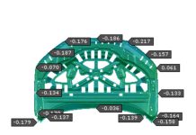
The resulting deviation of the part compared to the target geometry is now completely inside of the required tolerances, nearly net 0.0 with a few areas up to 0.35 mm. Only at the tube ends do we still find values of 1.4 mm and 0.8 mm. These areas are deemed not critical, as they are part of the tube addenda and therefore outside of part geometry.
A final robustness analysis, considering the unintended scattering of process parameters and material characteristics, indicates dimensional variation within the part is less than 0.35 mm. In combination with nominal springback deviation (all below 0.35 mm), it means that even with production noise the part will repeatably be within tolerance. The process layout and the compensated tool surfaces could be released with confidence.
The new methodology for springback compensation of hydroformed parts enables analysis of springback issues and definition of compensation strategies. This systematic approach helps identify root causes of springback and allows for designing and testing countermeasures for springback in each forming operation, before the final CAD tool design has been released. This approach significantly reduces the time-consuming CAD-based compensation, and reduces the tryout time, by eliminating deviations that otherwise prevent tool loading. The time saved in engineering and tryout results in lower costs and an earlier time-to-market for the final products.
| Title | Date | City/Country | Location | Presentation |
| New Developments in Hydroforming | May 10, 2016 | Fellbach, Germany | Schwabenlandhalle | Paper and Booth |
| New Developments in Sheet Metal Forming | May 10 – 11, 2016 | Fellbach, Germany | Schwabenlandhalle | Paper and Booth |






It is really interesting that there will be a certain amount of “spring back” after a pipe has been bent using the hydroforming technique. It sounds like addressing this effect by compensating for the expected difference should work pretty well. Do pipes exhibit this effect when then are formed with induction bending?
Kairi,
thank you very much for your interest in our AutoForm Blog. This kind of interaction with our readers is very important to us and part of our very own learing curve.
Concerning your question – indeed, companies applying this new methodology of virtual springback compensation for tubular parts are very satisfied about the good match of the simulated compensation and the practical application.
In particular for more complex geometries e.g. with several multidimensional bending steps the methodology significantly reduces their correction loops in tryout.
To answer your second question with regards to induction bending, here the springback effect in general can be expected to be much lower than with conventional bending, since the heat treatment significantly influences the amount of elastic stress in the part during and after the forming process. In most cases it might even be neglectable.
However, under certain boundary conditions –depending on parameters like material properties, ratio between wall thickness and tube diameter, bending angle and radius and process parameters like temperature and cooling time- the springback effect might exceed the specified quality tolerances of the part.
I hope this answers your question.
Best wishes
Cathérine