
Get What You Need Quickly with Simple and Easy-To-Use Geometry Creation Tools
As die process design engineers review everything we need to accomplish, it’s no wonder that it feels like an impossible task at times. Even when we’ve designed similar processes in the past, it can still seem like there is far too much to do. This is often because we’re being pushed to continually improve upon our accomplishments from the last project. To remain at the top of your industry, each design needs to be better in some way. Reduced blank size, use of thinner material, faster delivery of the tools, better initial part quality, use of a completely different material, and fewer processes are all typical improvement targets. The list goes on and on.

To put things in perspective, I like to compare this feeling to the simple analogy: “How do you eat an elephant?” You’re likely familiar with this analogy so to shorten the story…you do so by eating one small piece at a time. Step-by-step, you arrive at the task’s completion. Of course, I have never eaten an elephant — but it certainly seems impossible at first glance. But by breaking the problem down, it becomes less overwhelming. This means that we need the right tools to help us follow through on this problem solving approach.
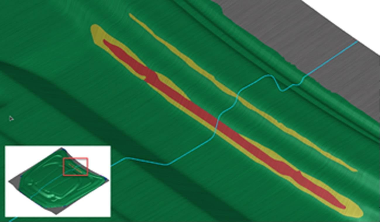
As an example to explore this idea, consider that you’re working on a new stamping die process. In this new design, you’ve met several of your targets, but now face a single formability problem. In the image below, the problem region is clearly visible as a split on the angled walls of the part.
One possible approach would be to go back and redesign the binder, addendum, and drawbeads. However, because you’ve achieved a highly effective design with one of the best material utilizations in the past 10 models, you would rather explore other options first. As it’s still early in the design cycle, there’s a chance that Product Design can change the design. What can we do to easily and effectively determine the feasibility of this option and communicate the requirements to Product Design? We have our first “piece of the elephant”!
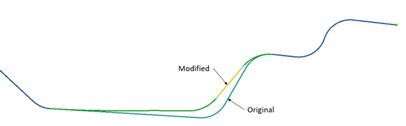
Using a Morph feature, we can try several countermeasures to the part design to reach an acceptable result. First, we use the Rigid Region Morph and rotate the wall to reduce the localized depth.
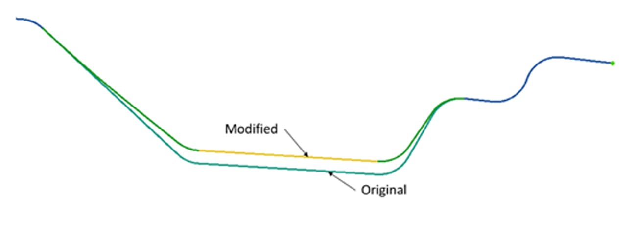
Next, we could use Rigid Region Morph to change the part’s overall depth. We know that some of these suggestions may not be acceptable to Product Design owing to performance. Therefore, we need to suggest the minimum adjustment that we know will fix the problem. This is an iterative process with multiple parameters, each with a range of values, so using the traditional approach of “guess and check” would take ages. Instead, we can use AutoForm-Sigma to be efficient with our time and explore all of the parameters together. You can set up a single design file with all possible adjustments and the resulting computations will give us a clear direction without user interaction.
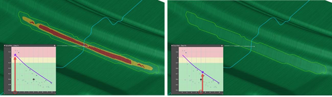
The results of this study provide solid confirmation of an effective countermeasure, a minimum part alteration, and takes very few man hours to complete. The specialized Morph feature enables us to land on a feasible countermeasure and understand the limits for this region. In addition, communication to Product Design becomes easy and exact. In the results pictured below, the nominal design with no modification is shown on the left, and the adjusted depth design is on the right. This indicates that about 4.38 mm of depth reduction will fully eliminate the split concern.
I must call attention to the importance of the design process used in this example. This was not the result of any single feature or software product; rather, the benefits arose from the combination of software interoperability, forming knowledge, and user execution. Leveraging these factors, you can make a design decision to meet all of the desired targets. There are so many resources available to us that we sometimes forget what’s possible, or become distracted by a single problem. To be an industry leader, daily work cannot be solely focused on an “OK” part. We cannot follow the same steps in the same order. Deeper study related to material reduction, efficiency, and robust processes must take more of our focus. Make use of any and all available tools, and create your own innovative path to success.
For a more detailed explanation of how to use these Morph features, customers can review the new helpful resources posted on the AutoForm ServiceCenter website. The AutoForm ServiceCenter is for customers only and provides online support resources such as eLearning, Frequently Asked Questions, “Best Practices”, and direct ability to submit issues to the AutoForm Technical Support Team. Of course, you can always contact your AutoForm Technical Support Team directly for more support and resources.


?")


